You are using an out of date browser. It may not display this or other websites correctly.
You should upgrade or use an alternative browser.
You should upgrade or use an alternative browser.
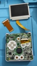
This is how to make AGS-101 screen work with AGS-001 motherboard.
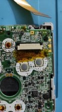
View attachment 88451 Cut this trace. This trace is on board revisions C/AGS-CPU-10 and C/AGS-CPU-11.
on C/AGS-CPU-01 trace goes under display connector.
View attachment 88452 Solder a wire to leftmost pin on the display connector.
View attachment 88453 Solder wires to motherboard and step-up converter, The GND connection is better shown in the next photo.
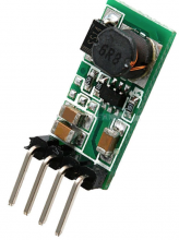
Step-up converter is Pololu U3V12F12 It's the smallest I found.
View attachment 88454 Use electrical tape to insulate step-up converter.
View attachment 88455Cut plastic to make room for step-up converter.
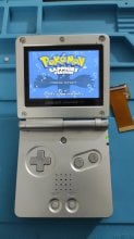
View attachment 88456 Done.
View attachment 88457 View attachment 88458 Comparison with GB Micro on brightest setting.
Is the regulator the only thing you need to buy? You use the old screen? Or buy a 101 screen? Also is there a more clear tutorial somewhere? Its hard to see where to soldor things. Thanks!!
Hi guys! I'm planning but have some questions.
With the voltage regulator powering the AGS101 screen, do you retain use of the potentiometer on the SP motherboard? I've modded a few AGB's and know the 101 screen can be quite annoying without using the potentiometer to get the image perfect.
I'm looking at buying one of the boards in the image attached which has 2 ground holes, one for voltage in and one for voltage out, which one should I use for this mod?
Attachments
Hello, is this mandatory? as far as I know, in the agb there is enough power supply to fit an AGS101 without all the extras pcbs
I've used this with a 001, it works fine:Hello, is this mandatory? as far as I know, in the agb there is enough power supply to fit an AGS101 without all the extras pcbs
https://funnyplaying.com/products/gbasp-ips-laminated-display-lcd-kits
If you want to use a regular '101' display, you will have to do special stuff.
But the modern IPS screens work fine without any work.
Not a laminated per se, but an AGS-101 fake (search for Fake AGS-101 LCD in a AGS-001)I've used this with a 001, it works fine:
If you want to use a regular '101' display, you will have to do special stuff.
But the modern IPS screens work fine without any work.
That is the one I have probably buyed in aliexpress, it appear to be a ips of some sort packed in a frame to resemble the original one
Hi, yesterday the cheap fake AGS-101 screen arrived. asi imagined is a ips kit. analizing AGS-CPU-11 board, discovered the lcd pinout pin 34 goes directly to 5v and pin 33 goes toa a various circuits. However, this fake screen comes with an adapter for classic gba and in these, pin 33 is bridged to pin 32 an pin 34 is bridged to pin 28. Also, from pin 34 is a cable soldered to solder in DA1 pin 2 in the original gba board. Any ideas? tested as described and the screen worked and backligted in the classic gba, also mako achieved this through a series o daysy chainig adaptors
OK, finished it a minute ago. After all the research, and investigation, I made it work!
I used a fake AGS-101 screen, it´s a ips panel inside an enclosure resembling an original AGS-101, I dont know if this has some to do, but at least keep that in mind. As a reference, youtuber makho uploaded that through a daisy chained adaptors the screen can backlight on its own. I searched de pinouts of various boards of AGB and AGS to compare and understand the conversions that where made. The fake screen came with a 32 pin adaptor so I routed the pin 33 & 34 to know where they are connected: pin 33 (U83) was routed to pin 32 (GND); Pin 34 (+5V) was routed to pin 28 (P2VDD)
using the base of the mod @Bazahazano and @steelseth has done, I proceded like this:
Soldered an enameled wire directly from a test point connected to pin 28 (P2VDD 13,5 v) as it was suposed to pull with the adaptor, and cut the trace of pin 34 (my board is AGS-CPU-11) to solder the other end in pin 34. Also, soldered a smd 500 ohm resistor (didnt had other value) in the mentioned ground, and using other piece of wire, soldered it to a through-hole connected to pin 33.
See the fotos to better understanding
This is the result:


The screen works very good, only the brightness button has little difference in high/low brightness, I dont know if it is because the 500 ohms resistor or other cause
I hope this was useful for someone
I used a fake AGS-101 screen, it´s a ips panel inside an enclosure resembling an original AGS-101, I dont know if this has some to do, but at least keep that in mind. As a reference, youtuber makho uploaded that through a daisy chained adaptors the screen can backlight on its own. I searched de pinouts of various boards of AGB and AGS to compare and understand the conversions that where made. The fake screen came with a 32 pin adaptor so I routed the pin 33 & 34 to know where they are connected: pin 33 (U83) was routed to pin 32 (GND); Pin 34 (+5V) was routed to pin 28 (P2VDD)
using the base of the mod @Bazahazano and @steelseth has done, I proceded like this:
Soldered an enameled wire directly from a test point connected to pin 28 (P2VDD 13,5 v) as it was suposed to pull with the adaptor, and cut the trace of pin 34 (my board is AGS-CPU-11) to solder the other end in pin 34. Also, soldered a smd 500 ohm resistor (didnt had other value) in the mentioned ground, and using other piece of wire, soldered it to a through-hole connected to pin 33.
See the fotos to better understanding
This is the result:


The screen works very good, only the brightness button has little difference in high/low brightness, I dont know if it is because the 500 ohms resistor or other cause
I hope this was useful for someone
Last edited by Crissaegrim87,
What value resistor would you think is better?The screen works very good, only the brightness button has little difference in high/low brightness, I dont know if it is because the 500 ohms resistor or other cause
I'm trying to do the same mod here...
Greetings!
I need clarification...OK, finished it a minute ago. After all the research, and investigation, I made it work!
I used a fake AGS-101 screen, it´s a ips panel inside an enclosure resembling an original AGS-101, I dont know if this has some to do, but at least keep that in mind. As a reference, youtuber makho uploaded that through a daisy chained adaptors the screen can backlight on its own. I searched de pinouts of various boards of AGB and AGS to compare and understand the conversions that where made. The fake screen came with a 32 pin adaptor so I routed the pin 33 & 34 to know where they are connected: pin 33 (U83) was routed to pin 32 (GND); Pin 34 (+5V) was routed to pin 28 (P2VDD)
using the base of the mod @Bazahazano and @steelseth has done, I proceded like this:
Soldered an enameled wire directly from a test point connected to pin 28 (P2VDD 13,5 v) as it was suposed to pull with the adaptor, and cut the trace of pin 34 (my board is AGS-CPU-11) to solder the other end in pin 34. Also, soldered a smd 500 ohm resistor (didnt had other value) in the mentioned ground, and using other piece of wire, soldered it to a through-hole connected to pin 33.
See the fotos to better understanding
This is the result:
View attachment 260089 View attachment 260090 View attachment 260091
The screen works very good, only the brightness button has little difference in high/low brightness, I dont know if it is because the 500 ohms resistor or other cause
I hope this was useful for someone
(P2VDD 13,5 v)
Also when you are referring to "pin 28", "pin 34", etc you mean the pins of the place where the ribbon cable of the display goes in, yes?
So:
1. pin 28 -> P2VDD on board (for 13V light power source?)
2. pin 33 -> BT- on board (=ground) + a resistor in between?
3. cut off pin 34
Is that right? At least for the mainboard that you got?
EDIT: This is (mostly) all wrong
Last edited by magic_maik,
I did it!
I used this step up converter because it has the extra feature that the sleep function will still work:
https://www.retromodding.com/products/game-boy-advance-ags-101-voltage-regulator
The display is this knockoff ags 101 IPS display, I believe it is the same that @Crissaegrim87 also bought
I used this step up converter because it has the extra feature that the sleep function will still work:
https://www.retromodding.com/products/game-boy-advance-ags-101-voltage-regulator
The display is this knockoff ags 101 IPS display, I believe it is the same that @Crissaegrim87 also bought
Attachments
Sorry for the late answer, been gone for too long.I need clarification...
This means you don't even need the 12v converter because the AGS-001 arleady has the 13V power source on the motherboard by itself? That would be awesome!
Also when you are referring to "pin 28", "pin 34", etc you mean the pins of the place where the ribbon cable of the display goes in, yes?
So:
1. pin 28 -> P2VDD on board (for 13V light power source?)
2. pin 33 -> BT- on board (=ground) + a resistor in between?
3. cut off pin 34
Is that right? At least for the mainboard that you got?
EDIT: This is (mostly) all wrong
I am glad that you succesfully made it work!
This setup worked, because this screen was a drop in for AGS101 based on a IPS panel. This lets the screen work with less power, hence it came with a ribbon adaptor for a no solder instalation on 32-pin GBA001 (tested by me).
So, if it works in AGB001, it pretty much has to work on AGS001. The thing is AGS001 DOES has 34 pins too, but with differrent voltage from AGS101, so cut a trace, lift a pin and solder wires and resistor was mandatory.
As you have noted, my mod makes "believe" the fake screen that it was intalled on 32-pin AGB001 so it worked just fine. The resistor between pin 33 and ground is there because in AGS001, the button works as a on/off switch instead of a dimmer like in AGS101. By putting that component there, you don´t open the circuit, just route via the resistor (mimicking to some excent AGS101 behaviour)
So, AGS001:
Board AGS-CPU-11
pin 34 -> 5v (it has 1 led for frontlight originally)
pin 33 -> Switch backlight (its a circuitry, buts acts like a switch)
pin 32 -> GND
pin 28 -> P2VDD (in schems, stated as a 13v source for contolling contrast, confirmed by the bridge in the ribbon adaptor that came along)
So, you lift (or cut its trace, depends on board type) pin 34 connector from board and bridge it to pin 28 (or some TP connected to it) to feed 13 v to the FAKE screen (not tested on original, I assume it will not work). Next, bridge pin 33 connector to GND though a resistor, so the voltage drops near the output originally intended from it and acts as a dimmer. DONE, ready to enjoy.
It will not be VERY bright, but that comes with few advantages:
* no need to source extra parts (step-up, doble sided tape, etc)
* battery life is extended compared to the step-up install
The step up is only needed if you are installing a original AGS101, as of others says, that thing will not backlight wit only pin 28 power (Can't confirm as I do not own one to test).
I have tested the sleep function in Super Mario 3 and it worked fine, the screen and sound goes off when you press L+R+SELECT
Hope this solved your doubts.
Last edited by Crissaegrim87,
Similar threads
- Replies
- 1
- Views
- 2K
- Replies
- 12
- Views
- 5K
- Replies
- 1
- Views
- 982
Site & Scene News
New Hot Discussed
-
-
27K views
Atmosphere CFW for Switch updated to pre-release version 1.7.0, adds support for firmware 18.0.0
After a couple days of Nintendo releasing their 18.0.0 firmware update, @SciresM releases a brand new update to his Atmosphere NX custom firmware for the Nintendo...by ShadowOne333 107 -
21K views
Wii U and 3DS online services shutting down today, but Pretendo is here to save the day
Today, April 8th, 2024, at 4PM PT, marks the day in which Nintendo permanently ends support for both the 3DS and the Wii U online services, which include co-op play...by ShadowOne333 179 -
17K views
GBAtemp Exclusive Introducing tempBOT AI - your new virtual GBAtemp companion and aide (April Fools)
Hello, GBAtemp members! After a prolonged absence, I am delighted to announce my return and upgraded form to you today... Introducing tempBOT AI 🤖 As the embodiment... -
14K views
The first retro emulator hits Apple's App Store, but you should probably avoid it
With Apple having recently updated their guidelines for the App Store, iOS users have been left to speculate on specific wording and whether retro emulators as we... -
13K views
Delta emulator now available on the App Store for iOS
The time has finally come, and after many, many years (if not decades) of Apple users having to side load emulator apps into their iOS devices through unofficial...by ShadowOne333 96 -
13K views
MisterFPGA has been updated to include an official release for its Nintendo 64 core
The highly popular and accurate FPGA hardware, MisterFGPA, has received today a brand new update with a long-awaited feature, or rather, a new core for hardcore...by ShadowOne333 54 -
12K views
Nintendo Switch firmware update 18.0.1 has been released
A new Nintendo Switch firmware update is here. System software version 18.0.1 has been released. This update offers the typical stability features as all other... -
11K views
"TMNT: The Hyperstone Heist" for the SEGA Genesis / Mega Drive gets a brand new DX romhack with new features
The romhacking community is always a source for new ways to play retro games, from completely new levels or stages, characters, quality of life improvements, to flat...by ShadowOne333 36 -
9K views
"Sonic 3" movie has wrapped production & Knuckles series gets its official poster
Quite a bit of news have unfolded in the past couple of days in regards to the Sonic franchise, for both its small and big screens outings. To start off, the...by ShadowOne333 27 -
9K views
Battle.net is required to play Diablo IV on PC Game Pass
This Thursday, Microsoft will be fulfilling one of its key promises from when it acquired Activision-Blizzard by bringing Diablo IV to Game Pass. It looks like it'll...
-
-
-
179 replies
Wii U and 3DS online services shutting down today, but Pretendo is here to save the day
Today, April 8th, 2024, at 4PM PT, marks the day in which Nintendo permanently ends support for both the 3DS and the Wii U online services, which include co-op play...by ShadowOne333 -
169 replies
GBAtemp Exclusive Introducing tempBOT AI - your new virtual GBAtemp companion and aide (April Fools)
Hello, GBAtemp members! After a prolonged absence, I am delighted to announce my return and upgraded form to you today... Introducing tempBOT AI 🤖 As the embodiment...by tempBOT -
111 replies
Nintendo takes down Gmod content from Steam's Workshop
Nintendo might just as well be a law firm more than a videogame company at this point in time, since they have yet again issued their now almost trademarked usual...by ShadowOne333 -
107 replies
Atmosphere CFW for Switch updated to pre-release version 1.7.0, adds support for firmware 18.0.0
After a couple days of Nintendo releasing their 18.0.0 firmware update, @SciresM releases a brand new update to his Atmosphere NX custom firmware for the Nintendo...by ShadowOne333 -
97 replies
The first retro emulator hits Apple's App Store, but you should probably avoid it
With Apple having recently updated their guidelines for the App Store, iOS users have been left to speculate on specific wording and whether retro emulators as we...by Scarlet -
96 replies
Delta emulator now available on the App Store for iOS
The time has finally come, and after many, many years (if not decades) of Apple users having to side load emulator apps into their iOS devices through unofficial...by ShadowOne333 -
74 replies
Nintendo Switch firmware update 18.0.1 has been released
A new Nintendo Switch firmware update is here. System software version 18.0.1 has been released. This update offers the typical stability features as all other...by Chary -
55 replies
Nintendo Switch Online adds two more Nintendo 64 titles to its classic library
Two classic titles join the Nintendo Switch Online Expansion Pack game lineup. Available starting April 24th will be the motorcycle racing game Extreme G and another...by Chary -
54 replies
MisterFPGA has been updated to include an official release for its Nintendo 64 core
The highly popular and accurate FPGA hardware, MisterFGPA, has received today a brand new update with a long-awaited feature, or rather, a new core for hardcore...by ShadowOne333 -
53 replies
Nintendo "Indie World" stream announced for April 17th, 2024
Nintendo has recently announced through their social media accounts that a new Indie World stream will be airing tomorrow, scheduled for April 17th, 2024 at 7 a.m. PT...by ShadowOne333
-
Popular threads in this forum
General chit-chat
-
 Psionic Roshambo
Loading…
 -
 The Real Jdbye
Loading…*is birb*
-
-
-
-
-
 @
Xdqwerty:
@salazarcosplay, I used apollo save tool to activate my ps3 offline so i could play a game that wasnt working
@
Xdqwerty:
@salazarcosplay, I used apollo save tool to activate my ps3 offline so i could play a game that wasnt working -
S @ salazarcosplay:from what I understood. you load up the piratged game. you the clear the syscalls, then you play
-
-
-
-
-
-
-
-
-
-
-
-
-
-
-
-
-
-
-
 @
Psionic Roshambo:
The only CoD game I played that I truly enjoyed was Black Ops 1, and only the single player game. I just found the plot pretty interesting.


