No 4v to Switch battery

Dukenukemx

Well-Known Member
OP
Newcomer
Joined
Nov 29, 2014
Messages
53
Trophies
0
Age
44
Location
Bergenfield, New Jersey
XP
217
Country
United States
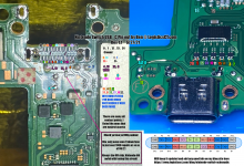
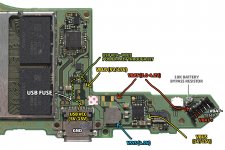
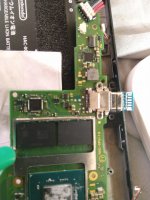
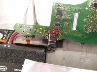
Trying to fix my nephews switch that he broke the power connector. I replaced the power connector and it won't turn on. I checked for shorts around the M92T36 chip, as well as the BQ24193 chip. I measure the battery while plugged in and it's 3.7V, but plugging in the charger doesn't change this. I can measure 5v coming in from the usb through the fuse. I replaced the 2R2 inductor near the charging port because it just fell off. The Switch will briefly show the Nintendo logo and turn off with the battery only. Also for some reason the main SoC chip gets warm while the charger is plugged in. Any idea what's wrong? Does anyone have access to a Switch board viewer like I've YouTubers with so I can trace why the battery doesn't get 4v?
 

Dukenukemx

Well-Known Member
OP
Newcomer
Joined
Nov 29, 2014
Messages
53
Trophies
0
Age
44
Location
Bergenfield, New Jersey
XP
217
Country
United States
Don't know if it helps but some information is here :
https://www.retrosix.wiki/first-stage-boot-short-checks
For other models, just search the forum.

The main SOC should not get warm when charging.
This might be a side effect of the shortage.

Are you sure that you properly mounted the power connector?
Thanks, I'll give that a look later. About that connector, I had a hard time with it. Particularly with the inner pads, as I ripped off a few of them. Pads 13, 14, and 15 from this photo. Pad 13 was still able to produce a ground, but 14 and 15 I had soldered wires and ran them to their needed location. I used solder mask paint to hold them on while I heated that section with a hot air tool. I did test all the connections and where they should go, and they work. I will remove the board to make sure the wires I ran didn't break off.
 

Attachments

  • switch-usb-c-connections.png
    switch-usb-c-connections.png
    5.6 MB · Views: 36

Dukenukemx

Well-Known Member
OP
Newcomer
Joined
Nov 29, 2014
Messages
53
Trophies
0
Age
44
Location
Bergenfield, New Jersey
XP
217
Country
United States
Got around to doing some testing and found some things. The pads that I had ripped off that was TX2 and TX+ were swapped by me by mistake. Easy enough mistake to fix, but then D+ and D- are also swapped. Those pads were not ripped off. My method of testing could have something to do with it? I'm using a USB test adapter that's more for USB 2.0, but the pins for the USB-C are still there and that's how I test the connections.

I also followed the diagram that @thesjaakspoiler linked and found that 5V went all the way to the yellow VBUS. The red VBAT is around 3.7V when plugged in and 3.5V when unplugged. The blue VSYS is 3.6V unplugged and 3.7V when plugged in. Also the 2R2 inductor is oriented the way I've seen most photos because I had no idea which direction it's suppose to face. No idea if the inductor has a polarity.

Post automatically merged:

Ok so I did some testing with the battery disconnected and the voltage is where you'd expect it to be from the diagram. So maybe everything is fine now? The diagram bellow shows that pins 6&7 are swapped from the underside. Maybe I should put the board back into the Switch and try it out?
switch port layout.jpeg

Post automatically merged:

With a multimeter you could check if there aren't any unintended bridges between adjacent pins.
You never know what your nephew did with the Switch.

I've seen someone managing to put a microUSB cable in the usb-C port.
Willing to bet my nephew tried to use an iPhone lightening cabled in the USB-C port. They don't believe in Android, so no microUSB.
Post automatically merged:

I'm finding that when I plug the charging cable one way, then no power goes to VBUS. Even though I find 5V from the USB fuse all the way to one of the two SN1 chips, but won't go to the other when the connector is flipped. Even though I tested the connector pins where VBUS should be and the 5V is present there too.

In the photo bellow the right chip gets the 5V, but not the left chip when the plug is turned around. These kinda look like they're heading to the M92T36 chip. So is it possible the M92 is bad but it somehow didn't short anything? Excuse me for the bad photo.
IMG_20231121_164613921.jpg

Post automatically merged:

Good news, the Switch turns on. I accidentally left it plugged in charging for a few hours and now it turns on. The only problem is that it doesn't charge with the connector both ways. I gotta figure out why.
 

Attachments

  • gRW6fC0hR5PdaZUV13cL6_system-power-points.jpg
    gRW6fC0hR5PdaZUV13cL6_system-power-points.jpg
    1.5 MB · Views: 43
  • IMG_20231121_120812719.jpg
    IMG_20231121_120812719.jpg
    1.9 MB · Views: 33
  • IMG_20231121_121045809.jpg
    IMG_20231121_121045809.jpg
    3.5 MB · Views: 29
Last edited by Dukenukemx,

Dukenukemx

Well-Known Member
OP
Newcomer
Joined
Nov 29, 2014
Messages
53
Trophies
0
Age
44
Location
Bergenfield, New Jersey
XP
217
Country
United States
I know I keep replaying to myself, but what the hell. So far I found a faulty connection on the top pins from the CCV2 connection. Which is strange because that pad was there and nothing should have happened to it. I ran a jumper wire because I'm not about to figure out why that pad isn't working. Now gotta put it together most of the way and see if the Switch can still be put into modded mode. One of the reasons I'm fixing this Switch was because it's an early model Switch that can be modded. Charging is one thing, but getting it to talk to my computer is another thing. Been a while since I've put this Switch into modded mode, so hopefully nothing has changed.
 

Attachments

  • IMG_20231122_141057608.jpg
    IMG_20231122_141057608.jpg
    8.4 MB · Views: 26

Dukenukemx

Well-Known Member
OP
Newcomer
Joined
Nov 29, 2014
Messages
53
Trophies
0
Age
44
Location
Bergenfield, New Jersey
XP
217
Country
United States
I tried to hook up the Switch to a PC and put it into hack mode by sending a payload but then it stopped working and Windows now says code 43 descriptor request failed. Anyone know why this is happening?
Post automatically merged:

Also it's charging very slowly. Last night it was at 10% and this morning it's at 25%. Something is very wrong.
 
Last edited by Dukenukemx,

Dukenukemx

Well-Known Member
OP
Newcomer
Joined
Nov 29, 2014
Messages
53
Trophies
0
Age
44
Location
Bergenfield, New Jersey
XP
217
Country
United States
Good news. The Switch is charging fast and Windows detects it and installs drivers for it. I replaced the M92 chip I bought off Amazon. I guess that means the M92 chip was indeed bad. Not bad enough to short as it's commonly known on the internet, but bad enough not to charge fast or to allow communication with a PC. Now to see if this continues over night.
 
  • Like
Reactions: impeeza

Dukenukemx

Well-Known Member
OP
Newcomer
Joined
Nov 29, 2014
Messages
53
Trophies
0
Age
44
Location
Bergenfield, New Jersey
XP
217
Country
United States
Awesome!
Thanks for sharing the details with us here.
That will help someone else with the same issue in the future.
As far as I can tell, there's no info on a M92 chip being bad that doesn't have shorts. I may have read a Reddit post where someone said it could still be bad even without shorts. Considering my situation, if anyone has a destroyed USB-C port, then they would need to consider also replacing the M92 because it's unlikely that it survived. Also consider getting a hot air station, which I did order off Aliexpress for this purpose and some other projects I have in mind. I was using a hot air gun meant for auto repair with a make shift reducer. It worked but... not very well.
 

Site & Scene News

Popular threads in this forum

General chit-chat
Help Users
  • No one is chatting at the moment.
    K3Nv2 @ K3Nv2: Lol rappers still promoting crypto