


ehem, its for research and development purposes, ehem.well thats awesome for us
wonder why they created this beauty
ehem, its for research and development purposes, ehem.well thats awesome for us
wonder why they created this beauty
i assume purple led is about emmc read failed. If it is true, then need to check the clk and cmd line. Usually bad solder, but if the solder is good, then reduce the noise by adding resistance value, or change the wire with a better one (copper not aluminium), or shorten the length.im in the process modding my lite, and i meet situation like you...
from your video, its not red color, looks like purple or pink . idk.
but i got same situation like you, which from blue > purple(maybe wasnt sure the color) , and lead to boot regular ofw.
but after that i resoldering my cables to resistor47, and i meet red led light=which make the screen only blackscreen, no boot to ofw. (after that i found my r47 soldering to rp2040 kinda bad joint/cracked, i use pinset and touch the R47 and it just fell off)
since im only testing it, i havent cut my cables from D0,CMD,CLK to R47 rp2040, and the cable pretty long, soon prob ill cut to a properly measure length.
(prob in my situation bad joint on the point, also bad soldering/cold soldering/cracked solder)
im pause and waiting my uv light and new soldering iron to continue this process, last time im too careful with the D0,CMD,CLK point, im afraid if i broke the point. (for now i remove all wiring from the RP2040 and my lite still can boot to OFW with no problem)
can someone explain what red led light on rp2040 means ?
also which type cable better for the point ?
for now im using enamel 0.1mm for the point D0 CMD CLK
Post automatically merged:
i saw from the pico guide, they add double resistor R47+R47 total R94, is it gonna fix ?
for purple led indication problem ??
Usually just use Continuity test between the resistor and the point on the motherboard.how to measure the point Dat0 CMD CLK with multimeter ?
i mean, once they are soldered to cables.
how to make sure they are properly soldered to cables ?
Not very good estimate, according to the exchange rate approximate price of 1.5$How much did it come out In production
Waveshare, Share our wave?LOL what?
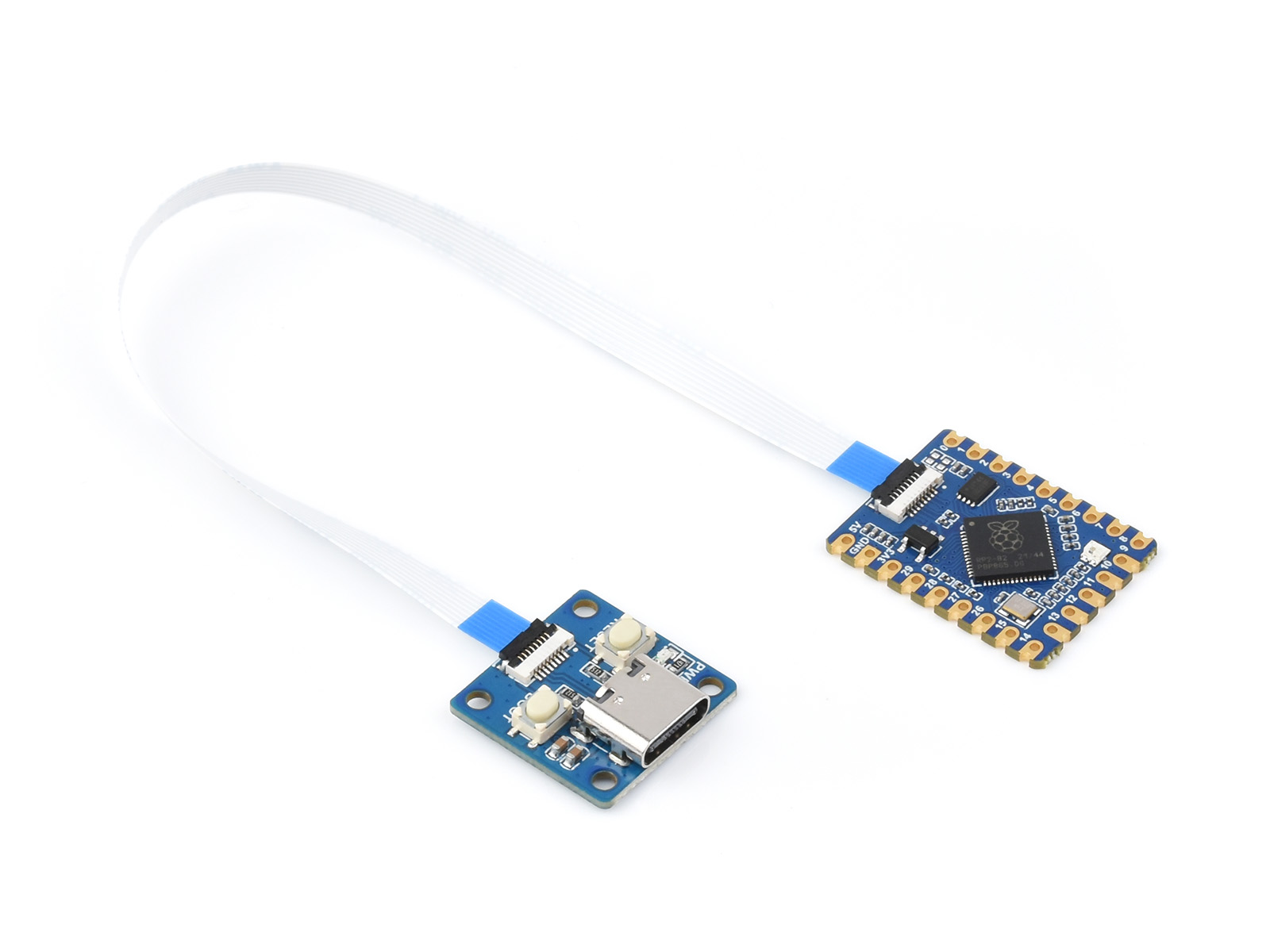
looks like Waveshare made a new "dev board" with detachable USB, resistors (47 ohm?) on pins 27, 28, 29, and "custom jumpers" on pins 24, 25.
https://www.waveshare.net/shop/RP2040-Tiny-Kit.htm
so adding one more 47+47 to the CMD and CLK ?i assume purple led is about emmc read failed. If it is true, then need to check the clk and cmd line. Usually bad solder, but if the solder is good, then reduce the noise by adding resistance value, or change the wire with a better one (copper not aluminium), or shorten the length.
Post automatically merged:
Usually just use Continuity test between the resistor and the point on the motherboard.
Resistor rarely broken, but to make sure do check resistance.
I don't remove the resistor, and its read 47 ohm all the three.
Great work. Can I ask, are you using P mosfets on these?
Yes you canInstead of MOSFETS can use the flexi tape v2? That has mosfets on it already?
For OLED TOTK Model.
Yes it works fineWill the hwfly flex cable lite + rp2040 zero works on switch v2?
Do we have a release for the cable?View attachment 368616
View attachment 368651
View attachment 368617
PICOFLY ИX module (verified)
https://github.com/SQc04/PICOFLY-X
Use easyeda PRO
https://easyeda.com/
The CPU cable will be released later
The resistor uses 0402 and is not recommended for novice welding
The circuit board is 0.8mm thick
V0.8.1+ supports jumpers, V1 V2 LITE OLED universal
I have the same problemJust tried to boot EmuMMC CFW and it says "A fatal error occured when running Fusée. Package1 seems corrupt!"
Also Warmboot says "Unknown pkg1 version. HOS version not supported"
What can I do now?
Add another resistor to the dat0Best regardsl
I have the same problem
No problem.@QuiTim sorry for mention you. May i ask you some questions? what difference between using single mosfet and dual mosfets? i'm trying to apply single mosfet method.
Im use to Mariko (V2) flex from V1 Erista with one mosfet made over 20+No problem.
To be honest I don't know. It seems that sometimes (for reasons unknown to me) one mosfet does not work.
I've only done 2 switches (both V2) with pico, and both of them worked with one mosfet (1st one with irf8714 the other one with irfah8342).
Use good wire, keep the length of the wire to minimum and solder good joints and I'm 99% sure it will work with one.
Well yes, i guess as long as the soldering is solid and the wires support the load, one mosfet is ok.Im use to Mariko (V2) flex from V1 Erista with one mosfet made over 20+


