So I got my Super NT by Analogue, but I never liked how the 2.4GHz receiver stuck out of the controller port (circled in red), so I thought to myself:
"The inside of the system is mostly empty space, surely I can solder it internally."

So I did, and here's the tutorial for that. (The "Tutorial" section doesn't have an "Other Consoles" category.)
You begin by taking a plastic pry tool of some kind (like a guitar pick or similar) and carefully peel up each corner of the rubber pad on the bottom, but only far enough to get to the screws, as we don't want to damage the double-sided sticky tape if it can be helped. You will need a TR10 Torx bit (star bit) for all the screws in this tutorial. The one I'm using came in the iFixit screwdriver kit and is labeled "TORX T10H" on the bit itself.

Once the 4 screws are out, keep the unit upside down and pull the top free, as the power and reset buttons will fall out otherwise. Set them aside. 3 more screws will get you the mainboard out, and you'll need 5 wires. I just had these Dupont wires handy, so that's what I used, but I highly recommend a much smaller gauge wire, 26 or 28 gauge will do nicely for this tutorial. I used my label maker to print labels, reminding me which port is for which player, because I'm a forgetful fuck. But that step isn't needed for most people.

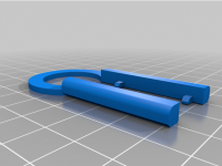
Now, there's no easy way to get to the PCB inside the receiver, but this 3D-printed tool might be of some help.


Otherwise you're just gonna have to cut away at it with something like flush-cutters until you can slide the top off.
Once inside, there will be 2 screws holding the PCB in place. Remove them and de-solder the yellow wires off the little PCB board, as we won't need them. Then solder the colored wires to the Analogue mainboard like this, tucking the wires as close to the solder pads as possible and heading towards the center of the board. If you don't tuck the wires as shown, you'll have difficulty reassembling the unit. You want the wiring to be tucked into the plastic channel of the bottom half of the shell.

Next, solder the other ends of the wires to the 8bitdo receiver PCB, like so:

Now tidy up your wiring, and secure the PCB down with some double-sided gorilla tape. Should look something like this when you're done.

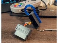
Before you reassemble the unit, go ahead and hook it up to the TV and make sure the controller is in working order, before buttoning everything back up.
Now everything works as intended, without a visible receiver. And the bonus: You can still use the controller port for wired controllers, as intended. I only did this for Player 1's controller port, but both can be done in a similar fashion.
Here it is in action:
Hope someone finds this useful.
"The inside of the system is mostly empty space, surely I can solder it internally."
So I did, and here's the tutorial for that. (The "Tutorial" section doesn't have an "Other Consoles" category.)
You begin by taking a plastic pry tool of some kind (like a guitar pick or similar) and carefully peel up each corner of the rubber pad on the bottom, but only far enough to get to the screws, as we don't want to damage the double-sided sticky tape if it can be helped. You will need a TR10 Torx bit (star bit) for all the screws in this tutorial. The one I'm using came in the iFixit screwdriver kit and is labeled "TORX T10H" on the bit itself.
Once the 4 screws are out, keep the unit upside down and pull the top free, as the power and reset buttons will fall out otherwise. Set them aside. 3 more screws will get you the mainboard out, and you'll need 5 wires. I just had these Dupont wires handy, so that's what I used, but I highly recommend a much smaller gauge wire, 26 or 28 gauge will do nicely for this tutorial. I used my label maker to print labels, reminding me which port is for which player, because I'm a forgetful fuck. But that step isn't needed for most people.
Now, there's no easy way to get to the PCB inside the receiver, but this 3D-printed tool might be of some help.
Otherwise you're just gonna have to cut away at it with something like flush-cutters until you can slide the top off.
Once inside, there will be 2 screws holding the PCB in place. Remove them and de-solder the yellow wires off the little PCB board, as we won't need them. Then solder the colored wires to the Analogue mainboard like this, tucking the wires as close to the solder pads as possible and heading towards the center of the board. If you don't tuck the wires as shown, you'll have difficulty reassembling the unit. You want the wiring to be tucked into the plastic channel of the bottom half of the shell.
Next, solder the other ends of the wires to the 8bitdo receiver PCB, like so:
Now tidy up your wiring, and secure the PCB down with some double-sided gorilla tape. Should look something like this when you're done.
Before you reassemble the unit, go ahead and hook it up to the TV and make sure the controller is in working order, before buttoning everything back up.
Now everything works as intended, without a visible receiver. And the bonus: You can still use the controller port for wired controllers, as intended. I only did this for Player 1's controller port, but both can be done in a similar fashion.
Here it is in action:
Hope someone finds this useful.