Picofly AIO Thread

QuiTim

Well-Known Member
Member
Joined
Mar 30, 2023
Messages
757
Trophies
0
XP
1,179
Country
Albania
Hi guys, to receive the DAT0 adapters quickly, how can I do?
I can only find them on aliepress.
On ebay, amazon I can not.
Am I looking wrong?
If so, is one the other or should I take something in particular?
If I wanted to try without the adapter, which pin should I connect a jumper to?
aliexpress and get the "4 anchor" one as in photo
permanent dat0 pin same as in photo
 

Attachments

  • 4an.jpg
    4an.jpg
    29.1 KB · Views: 31
  • Dat0.jpg
    Dat0.jpg
    147.8 KB · Views: 31
  • Like
Reactions: cicci084

Vivi34

New Member
Newbie
Joined
May 15, 2023
Messages
2
Trophies
0
Age
35
XP
41
Country
Spain
Hi everybody. First of all, thanks for clarifying the installation process. I got a rp2040 installed on my Mariko and it works flawlessly. There is however one thing that I think should not happen. Whenever I poweroff from the menu in ofw, next time I push the power button, the screen stays black. Then, I have to push power button for a few seconds and next time I turn the console on, hekate boots normally.
Any ideas about what could be causing this?
 

agus

Active Member
Newcomer
Joined
Apr 15, 2016
Messages
41
Trophies
0
Age
37
XP
113
Country
Indonesia
Lot of people already use IR8342 mosfet, and succeed.
Hwfly flex cable using mosfet too, kind of forgot the names np616 or similar like that.

I use one pieces of IR8342 on lite, and its successfull.
Now i try to change with alternative mosfet, alternative method, alternative point.
I use 2 mosfet. and it failed. .. if you use 1 moafed it will damage the switch parts. i don't want that
 

QuiTim

Well-Known Member
Member
Joined
Mar 30, 2023
Messages
757
Trophies
0
XP
1,179
Country
Albania
I use 2 mosfet. and it failed. .. if you use 1 moafed it will damage the switch parts. i don't want that
Can you please let us know why using single mosfet damages switch parts or at least the source of this information?
There are alot of people who used only one mosfet on multiple installations (including myself) and nobody reported a problem yet.
 

abal1000x

Well-Known Member
Member
Joined
Jun 5, 2022
Messages
1,070
Trophies
0
XP
1,405
Country
Gaza Strip
I use 2 mosfet. and it failed. .. if you use 1 moafed it will damage the switch parts. i don't want that
The original setup is using 1 mosfet lol.

Basically this is voltage glitch or Fault Injection technique. (CMIIW)

The mosfet function as a 'controlled switch' which take off the current which originally powered the processor, for a certain duration at a certain time in some time reference. For simplicity the mosfet Short Circuit the processor vdd rail to gnd. Seems scary, right?

If some people said, they need 2 mosfets. I suspect that their cable is not good enough to deliver high current to the mosfet. In the datasheet the mosfet could flows 8.5A. Doubled the mosfet, just doubling the capability to flows the 8.5A. But the original setup only use 1, so 8.5A is sufficient. Even if you have 2 mosfets but if the cable can't deliver the necessary current, the glitch also failed.

Now goes to the wire, for 0.1mm diameter of copper, the fusing current is 2.6A, 0.2mm - 7.3A, 0.3mm - 12.3A.
If you want to be saved use 0.3mm (this is what i use in the first trial), its more than 8.5A the mosfet max current. I use this and worked. People use 0.2mm and confirmed its also worked. Using 0.1mm diameter copper wire is not recommended. And if you use aluminium cable, than you need to find a bigger diameter then the copper calculation.

So using 2 mosfet or 1 mosfet do not correlate with damaging switch parts. (You do the mosfet is already risk damaging the apu) The correlation is lay on the one who install it, no matter its 1, or 2, or 3, or whatever mosfets you use.

Again CMIIW.
 

btjunkster

Member
Newcomer
Joined
May 15, 2023
Messages
6
Trophies
0
Age
44
XP
75
Country
United States
Hi all. I have an animal crossing v2. Installed Picoboot but kept getting blue light then yellow light and nothing happens. I have to then hold power button for 10 seconds or so before the console will allow me to reboot again.

I have double checked the Dat0 connection and it seems fine.

When I removed Picofly. The console is able to boot normally.

Appreciate any pointer at all. I read somewhere EMMC could be incompatible. How do I check that?
 

MertX2

Member
Newcomer
Joined
Oct 16, 2022
Messages
17
Trophies
0
Age
35
XP
218
Country
Germany
Ordering a normal carrier board for the mosfets rn to make the install a bit easier and save myself some headaches on further installs, will share the files if it ends up working and anybody would like it(not that it would be hard to replicate).
 

cicci084

Well-Known Member
Member
Joined
Apr 1, 2023
Messages
146
Trophies
0
Age
44
XP
239
Country
Italy
aliexpress and get the "4 anchor" one as in photo
permanent dat0 pin same as in photo
Hi guys. I have a stencil for reballing old Samsung s4.
I think it's the same layout/pinout as the switch's mmc. (photo)
Are you able to
Confirm?

In all cases I bought a used oled switch, I hope to be able to mod it with this stencil, I'll update you as soon as it arrives.
 

Attachments

  • IMG-20230515-WA0043.jpg
    IMG-20230515-WA0043.jpg
    165.6 KB · Views: 28

QuiTim

Well-Known Member
Member
Joined
Mar 30, 2023
Messages
757
Trophies
0
XP
1,179
Country
Albania
Hi guys. I have a stencil for reballing old Samsung s4.
I think it's the same layout/pinout as the switch's mmc. (photo)
Are you able to
Confirm?

In all cases I bought a used oled switch, I hope to be able to mod it with this stencil, I'll update you as soon as it arrives.
I see 153 holes so i guess it's the same :)
Good luck.
 

lightninjay

Well-Known Member
Member
Joined
Mar 28, 2023
Messages
560
Trophies
0
Age
31
XP
1,392
Country
United States
View attachment 371590
WELP 😃
Post automatically merged:

what the hell happened :cry: i swear i did everything perfectly lol
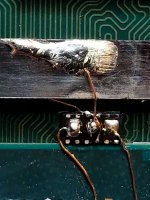
Sure looks like your CPU wire (Gate) at the top of the photo, is bridged straight across the crusty Drain pad that appears to be bridging the ENTIRE FACE OF THE MOSFET. Throw out that top mosfet and try again with more flux please. The bottom mosfet looks decent... However it looks like you didn't even hook the Gate wire to the CPU, so it's pointless.
 
  • Haha
Reactions: LogicalMadness

naldo29

Well-Known Member
Member
Joined
Jan 10, 2017
Messages
166
Trophies
0
Age
49
XP
320
Country
United States
Sure looks like your CPU wire (Gate) at the top of the photo, is bridged straight across the crusty Drain pad that appears to be bridging the ENTIRE FACE OF THE MOSFET. Throw out that top mosfet and try again with more flux please. The bottom mosfet looks decent... However it looks like you didn't even hook the Gate wire to the CPU, so it's pointless.
the gate for the bottom one broke off when i was checking for damage, and the top gate well, i added soldering mask so i thought it wouldnt make a connection plus, my cable was enameled so i also didnt think it would short out. Also i got a question, what do you mean by more flux? what are you reffering to?
 

lightninjay

Well-Known Member
Member
Joined
Mar 28, 2023
Messages
560
Trophies
0
Age
31
XP
1,392
Country
United States
the gate for the bottom one broke off when i was checking for damage, and the top gate well, i added soldering mask so i thought it wouldnt make a connection plus, my cable was enameled so i also didnt think it would short out. Also i got a question, what do you mean by more flux? what are you reffering to?
I see the green solder mask on the "bottom" mosfet, but the top looks all crusty and grey. Do you have two different soldermasks? My point of use more flux, is meaning that your solder joints look crusty and dull. More flux will clean up your solder joints and make things like shiny, pretty, and much more functioning.

PLEASE don't respond with "What is flux?" I might actually lose it...

This is what your install should have ended up looking like with proper flux and temperatures, with the right soldering tip, and tweezers to hold pre-tinned wires in place.
IMG_20230506_163758.jpg
 
Last edited by lightninjay,

naldo29

Well-Known Member
Member
Joined
Jan 10, 2017
Messages
166
Trophies
0
Age
49
XP
320
Country
United States
I see the green solder mask on the "bottom" mosfet, but the top looks all crusty and grey. Do you have two different soldermasks? My point of use more flux, is meaning that your solder joints look crusty and dull. More flux will clean up your solder joints and make things like shiny, pretty, and much more functioning.

PLEASE don't respond with "What is flux?" I might actually lose it...

This is what your install should have ended up looking like with proper flux and temperatures, with the right soldering tip, and tweezers to hold pre-tinned wires in place.
View attachment 371595
whats flux? Im joking lol i just wanted to know what exactly you meant by that. also umm.... the mask looks like that because the mosphet exploded lol. heres a picture of how it looked before everything went to shit. Also that is a very smart idea of what you did there, you combined both gates into one single cable, i should do that next time.
1684130834634-png.371439
 

lightninjay

Well-Known Member
Member
Joined
Mar 28, 2023
Messages
560
Trophies
0
Age
31
XP
1,392
Country
United States
whats flux? Im joking lol i just wanted to know what exactly you meant by that. also umm.... the mask looks like that because the mosphet exploded lol. heres a picture of how it looked before everything went to shit. Also that is a very smart idea of what you did there, you combined both gates into one single cable, i should do that next time.
1684130834634-png.371439
The only way to install both gates in the manner I did, is to be very comfortable with tinning magnet wire precisely, because it requires tinning both the tip, and a small portion away from the tip, without tinning/ruining the insulation in the short span in-between that runs near the Source pads. Always ALWAYS check these points for shorts to each other before testing for a glitch. Otherwise, as you've learned, your mosfet can EXPLODE.
 

zZMaCK1eZz

Member
Newcomer
Joined
Apr 12, 2023
Messages
5
Trophies
0
Age
31
XP
63
Country
Mexico
Hello everyone! I'm here seeking your help. I installed Picofly on a V1.1, and the glitch switch works normally. However, when I press Vol+ and Vol- to enter the original system, I get a blue screen. When I connect the reader with the SD card, the screen stays black. I have checked the soldering, and everything seems fine. I have also inspected the memory card reader connector, and nothing appears to be damaged. I have even tried removing everything to perform a factory reset as recommended, but when I turn it on, I still get the blue screen. I'm really at a loss here. I've done several installations before, and this is the first time this has happened. Can you please help me?
 

Attachments

  • WIN_20230515_13_26_15_Pro.jpg
    WIN_20230515_13_26_15_Pro.jpg
    132.2 KB · Views: 30
  • WIN_20230515_13_26_06_Pro.jpg
    WIN_20230515_13_26_06_Pro.jpg
    131.5 KB · Views: 31
  • IMG20230515132243.jpg
    IMG20230515132243.jpg
    1.7 MB · Views: 37

cgtchy0412

Well-Known Member
Member
Joined
Apr 26, 2023
Messages
287
Trophies
0
Age
41
XP
438
Country
Indonesia
I've try the 6512 this weekend and failed (blue-cyan).
Need further examination though, until next week, or whenever i have spare time :D
confirmed that aon6512 is indeed working, but the glitch time is like 15 second, already tried multiple time, each took that long. Any ideas? maybe increasing the R value? or its just mosfet uniqueness.
But i think i already have the candidate for replacement and it is aon7400.. easier to find for me, and work as it should, glitch time also like 2 second.
3 mosfet more to try nonetheles.
 

Attachments

  • 20230516_072622.jpg
    20230516_072622.jpg
    1.3 MB · Views: 38

blackheartme

Well-Known Member
Newcomer
Joined
May 28, 2021
Messages
51
Trophies
0
Age
35
XP
276
Country
Indonesia
lmao
Post automatically merged:

im sorry but this "ground" pinout.... its impossible to tin.... i cant do it. IT WONT STICK and yes im using flux. how can i make it stick?
scaped it a bit, we good now.
View attachment 371428
Post automatically merged:

View attachment 371439what do yall think?
change the source point to another ground like the chassis as per arrow below, ive been there lol
 

Attachments

  • Capture.PNG
    Capture.PNG
    960.1 KB · Views: 32

abal1000x

Well-Known Member
Member
Joined
Jun 5, 2022
Messages
1,070
Trophies
0
XP
1,405
Country
Gaza Strip
confirmed that aon6512 is indeed working, but the glitch time is like 15 second, already tried multiple time, each took that long. Any ideas? maybe increasing the R value? or its just mosfet uniqueness.
But i think i already have the candidate for replacement and it is aon7400.. easier to find for me, and work as it should, glitch time also like 2 second.
3 mosfet more to try nonetheles.
Nice finding. I think its more the characteristics of the glitch.

The rds must be at some range for it to be work, flawlessly.
[email protected]
AON6512: 2mΩ (15s)
NP2016: 9 mΩ (?)
IRF8714: 10.9 mΩ (3-4s)
AON7400: 13 mΩ (2s)
IRF8342: 20 mΩ (1-3s)

From that data, the best Rds should be around 10 mΩ
If you try other mosfet, please let us know the result.
Thank you for the sharing information.
 
Last edited by abal1000x,
  • Like
Reactions: Phantomas77

cgtchy0412

Well-Known Member
Member
Joined
Apr 26, 2023
Messages
287
Trophies
0
Age
41
XP
438
Country
Indonesia
Nice finding. I think its more the characteristics of the glitch.

The rds must be at some range for it to be work, flawlessly.
[email protected]
AON6512: 2mΩ (15s)
NP2016: 9 mΩ (?)
IRF8714: 10.9 mΩ (?)
AON7400: 13 mΩ (2s)
IRF8342: 20 mΩ (1-3s)

From that data, the best Rds should be around 10 mΩ
If you try other mosfet, please let us know the result.
Thank you for the sharing information.
Or maybe we need to also pay attention to these switching characteristic value?
Also it can be that different brand states or we call it promote their specs differently.
Will update tomorrow.
 

Attachments

  • Untitled.png
    Untitled.png
    19.9 KB · Views: 29
Last edited by cgtchy0412,

Site & Scene News

Popular threads in this forum

General chit-chat
Help Users
  • AncientBoi
  • BakerMan
    I rather enjoy a life of taking it easy. I haven't reached that life yet though.
    AncientBoi @ AncientBoi: [uploads TP] :D