


You can use a single mosfet, 2 makes makes it a bit more stable, based on discussions in this thread. You may also get better luck if you tried without insulation and have the copper strands twisted for more rigidity.This is definitely one of the hardest welds I've tried to make. and I don't have a 0.2mm cable to make it, only 0.1mm and this one is 30awg.
what is the problem of doing only 1 mosfet?
You are using an out of date browser. It may not display this or other websites correctly.
You should upgrade or use an alternative browser.
You should upgrade or use an alternative browser.
Staff Posts
Recent threadmarks
sharing files
Important Posts
Recent threadmarks
Firmwares
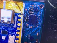
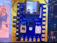
1. The hwfly rp2040 is officially for sale on hwfly aliexpress storefront nowi see,but i dont have the skills for use that picotool,i need can update then via usb BEFORE, install,and thats right,for use tolbox the chip must be installed,thats the problem,i need update then before install in the switch,just like my old chips,the chip in the picture works perfect,never have any single problem,they conect to pc perfect without problems,but suplier say factory is no make then anymore,now they fabric the hwflyrp2040 instead
2. the chip comes with 2.61 firmware. Its not relatively old firmware, why bother updating it first?

I think now I've had a success.You can use a single mosfet, 2 makes makes it a bit more stable, based on discussions in this thread. You may also get better luck if you tried without insulation and have the copper strands twisted for more rigidity.
 01.12.22.jpg")

Do you happen to have a diagram for the Fan assembly on the OLED? I want to know where to look :'soooh broken firms are not fun. - I'll poke ansem later today about it
I'm guessing something on the fan circuit is dead or shorted
Thank you for the time you spend writing this. A good way for me to start is changing the tip like you recommended.You are welcome.
As for capacitor I would suggest,
- Weller RTP 001 solder tip (you can get a custom pen for these tips if you don't want to buy the whole station, let me know if you need the link) or
- JBC C115118 tip (you can pair these with alot of chinese stations)
You can cheap out on station but the tip has to be genuine
- Good flux (it makes a difference)
- Sn63/Pb37 or preferably Sn62Pb36Ag2 solder
Soldering iron to 370-400, tin the mosfet wire then add flux to cap and add some solder to the tip of the iron and just slightly touch the side of the cap and boom you added some low melt solder to cap. Now pres the tinned wire to cap and again just a slight touch (2sec max) and there you have it.
I guarantee that you will nail it
Now don't get me wrong, there are people here that can solder this with their left foot holding a fork heated over stove but I'm not one of those guys so having the right tools (in this case read expensive) puts you closer to the pro league
Regarding MOSFETs, Would you guys recommend I solder directly into the cap or remove it entirely and solder directly to the pad?

here in many post say very clear about update to the most newer firmware,i do that in the old hwfly before every install1. The hwfly rp2040 is officially for sale on hwfly aliexpress storefront now
2. the chip comes with 2.61 firmware. Its not relatively old firmware, why bother updating it first?
I'm getting a yellow color when flashing rp2040. Even after bridging. Is that new?

Can you give a link?1. The hwfly rp2040 is officially for sale on hwfly aliexpress storefront now
2. the chip comes with 2.61 firmware. Its not relatively old firmware, why bother updating it first?
As far as i know, hwfly official store is gone since the accident of the totk leak
That's a good question that I couldn't find an answer for. When doing a flex cable, I get a 0.5-0.9v on the third wire, but when using mosfet, nothing. Zero. How can I check my MOSFET work before booting it?I think I managed to make the mosfets, is there any way to test with the multimeter? I did the diode test, with the mosfet without the wires and with the wires, the red wire, continuity with the green one? is correct ?
View attachment 372567View attachment 372568
@rehius
I've read the `glitch_try_offset` function.
I might be wrong understanding it. But shouldn't be the variable `edges` added to the `offset` parameter?
```
int gres = do_glitch(offset, *width, 300, 6);
```
should be
```
int gres = do_glitch(offset + edges, *width, 300, 6);
```
I have read the code and its beautiful. Thanks again for sharing.

No, the glitch_try_offset is a single attempt for the specific offset. There we try that offset several times.I might be wrong understanding it. But shouldn't be the variable `edges` added to the `offset` parameter?
The second glitch parameter - width - should be on the very edge of "timeout" (when the glitch is too strong, CPU halts) and "failure" (when the glitch is too weak, and CPU had no reaction).
There we are varying width back and forth to swing around that point. Number of "edges" is amount of times we pass through the optimal glitch positions, as I found, that is a good point of reference for amounts of tries for the specific offset.
Since each offset should be tried many many times, there are tons of tricks for attempt time reduction (to speed up the whole process)
Thanks for the reply. Now I understand.No, the glitch_try_offset is a single attempt for the specific offset. There we try that offset several times.
The second glitch parameter - width - should be on the very edge of "timeout" (when the glitch is too strong, CPU halts) and "failure" (when the glitch is too weak, and CPU had no reaction).
There we are varying width back and forth to swing around that point. Number of "edges" is amount of times we pass through the optimal glitch positions, as I found, that is a good point of reference for amounts of tries for the specific offset.
Since each offset should be tried many many times, there are tons of tricks for attempt time reduction (to speed up the whole process)
Because i read from the `prepare_random_array()` that the offset are generated from 6200-6900 with 10 step (6200, 6210, 6220...)
I thought maybe when the `step` (to find the proper `width`) already precised (step = 1) then the code will make a fine step on the offset (6200, 6201, 6203). I also guess, if the offset change, maybe the width should also need to be 'searched' again.


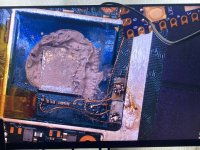
okay well that good then.It is thin enough to fit under the shield without any bulge. The green adapter comes pre-balled on both sides so there's no reballing needed.
The installation process is:
- Detach emmc (add flux around it, then heat 160c 1 minute, 260c 1 minute, 360c 1 minute, then 400c for a few seconds until it detaches if it hasn't already)
- Clean emmc pads on the motherboard with solder wick
- Clean emmc with solder wick
- Add flux to the emmc pads on the motherboard and align green adapter on top. heat 160c 1 minute, 260c 1 minute, 360c 1 minute. Then it should be nicely attached.
- add flux on emmc pads on top of the green adapter and align emmc on top. heat 160c 1 minute, 260c 1 minute, 360c 1 minute. Then it should be nicely attached.
- solder dat0, clk, cmd wires on the nice, large solder pads of the green adapter.
Post automatically merged:
The Picofly RP2040 board in hwfly-style are available from the "main" hwfly sales store on aliexpress now. https://www.aliexpress.com/item/1005005591152539.html
i Know the process but thank u :-)
yeah i still will always prefer the perm dat = without the green adapter just cause of the delivery time
Two long debug pulses. CLK is connected properly. What could be a problem? How do i check if mosfets connected?
P.S. Yeah, i know, it's messy. But everything connected properly.
P.S. Yeah, i know, it's messy. But everything connected properly.
Attachments
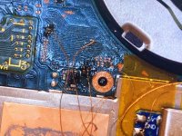
first of all clean ur flux after solderingTwo long debug pulses. CLK is connected properly. What could be a problem? How do i check if mosfets connected?
P.S. Yeah, i know, it's messy. But everything connected properly.
second use shorter wires for ur mosfet , what wire diameter is that ? looks like 0.1mm if thats the case u need atleast 0.2mm wire
also u can use 0.1mm wire for 3,3v specially if u use 0.1mm for ground then also use the same wire thinkess for 3v
Last edited by Dee87,

This doesn't really answer your question, but those "OATO" adapters have been mentioned in this thread before. The point of contact with the ball under the IC seems to be too wide and/or poorly cut, potentially causing shorts with the ones next to it.Hi, is this dat0 position fine? The diode value is .62v
The so-called "four anchor" adapters, or even the "corner style" adapters, are generally preferred. I guess that (and the obvious misspell of "DAT0") is why the "OATO" is so much cheaper than the others.
FWIW, I have the "OATO" adapters on hand, along with everything else to perform this mod right now, and yet I'm waiting for a shipment of the "four anchor" adapters before attempting it. Just my 2¢.

Looks much better now.I think now I've had a success.
View attachment 372572
You could also do just one mosfet in the future, and if it does not work then you add edhe second one.
So 1 mosfet but both capacitors.
Post automatically merged:
This has been mentioned earlier if I remember correctly and it was recommended to keep the cap if possible since it's better for the apu in the long run especially if you play high resource demanding gamesThank you for the time you spend writing this. A good way for me to start is changing the tip like you recommended.
Regarding MOSFETs, Would you guys recommend I solder directly into the cap or remove it entirely and solder directly to the pad?
Post automatically merged:
I got green on 2.7. I dont know if this changed in 2.72. There should be a changelog on page 78I'm getting a yellow color when flashing rp2040. Even after bridging. Is that new?
*Edit: lightninjay already anwered this, yellow is OK now in the new firmware.
I second @Nephiel opinion. The reading is correct but those adapters are not good.Hi, is this dat0 position fine? The diode value is .62v
View attachment 372589View attachment 372588View attachment 372587
I had an Oled where I spent 3 days trying to figure out what was happening and turns out dat0 was giving some short under emmc.
Maybe it's the photo but I can already see some deformation on the upper left side of the adapter.
Last edited by QuiTim,
Good afternoon I ran into an interesting problem.
Switch OLED (FW 2.67). DAT0 adapter, the contact is well soldered. Diode test value 0.800v. Same value when pin is already soldered to rp2040 Zero (wire 0.1mm).
Approximately once a week at the next reboot of the switch, I get the yellow color of the LED and it loads only in OFW.
I check the contact to the ground in the DAT0 diode mode and I already get about 1.500v. Strange.
I just unplug the DAT0 wire from rp2040 and immediately solder it back. Immediately a diode test shows the correct 0.800v. Everything works fine again until the next similar event.
I tried to change the wire from the adapter to rp2040 to a thinner one, I also changed the resistor (the correct one is 47Ohm), but the problem repeats regularly.
Some kind of mysticism, any ideas why this happens and how I could avoid this in the future? Can I replace the rp2040 board?
I don't know it this a variation of the same issue but a similar one was fixed with the new firmware so maybe you should try to update to 2.72 first.Good afternoon I ran into an interesting problem.
Switch OLED (FW 2.67). DAT0 adapter, the contact is well soldered. Diode test value 0.800v. Same value when pin is already soldered to rp2040 Zero (wire 0.1mm).
Approximately once a week at the next reboot of the switch, I get the yellow color of the LED and it loads only in OFW.
I check the contact to the ground in the DAT0 diode mode and I already get about 1.500v. Strange.
I just unplug the DAT0 wire from rp2040 and immediately solder it back. Immediately a diode test shows the correct 0.800v. Everything works fine again until the next similar event.
I tried to change the wire from the adapter to rp2040 to a thinner one, I also changed the resistor (the correct one is 47Ohm), but the problem repeats regularly.
Some kind of mysticism, any ideas why this happens and how I could avoid this in the future? Can I replace the rp2040 board?
Last edited by QuiTim,
Similar threads
- Replies
- 5
- Views
- 2K
- Replies
- 2
- Views
- 838
- Replies
- 42
- Views
- 7K
Site & Scene News
New Hot Discussed
-
-
39K views
New static recompiler tool N64Recomp aims to seamlessly modernize N64 games
As each year passes, retro games become harder and harder to play, as the physical media begins to fall apart and becomes more difficult and expensive to obtain. The... -
18K views
Majora’s Mask PC port 2Ship2Harkinian gets its first release
After several months of work, the Harbour Masters 64 team have released their first public build of 2Ship2Harkinian, a feature-rich Majora's Mask PC port. This comes... -
17K views
Anbernic reveals the RG35XXSP, a GBA SP-inspired retro handheld
Retro handheld manufacturer Anbernic has revealed its first clamshell device: the Anbernic RG35XXSP. As the suffix indicates, this handheld's design is inspired by... -
17K views
Mario Builder 64 is the N64's answer to Super Mario Maker
With the vast success of Super Mario Maker and its Switch sequel Super Mario Maker 2, Nintendo fans have long been calling for "Maker" titles for other iconic genres... -
13K views
The founder of Oculus is releasing a $199 FPGA Game Boy system
Palmer Luckey is known for his pursuits into the world of virtual reality, having founded Oculus and designed the Rift VR headset. Prior to the $2 billion dollar... -
13K views
Ubisoft reveals 'Assassin's Creed Shadows' which is set to launch later this year
Ubisoft has today officially revealed the next installment in the Assassin's Creed franchise: Assassin's Creed Shadows. This entry is set in late Sengoku-era Japan... -
13K views
RetroArch is now available in the Apple Store for iOS devices
Another day, another great emulator that makes its way into the Apple Store for more users to enjoy. With Apple opening its store up to videogame emulators earlier...by ShadowOne333 58 -
12K views
The Kingdom Hearts games are coming to Steam
After a little more than three years of exclusivity with the Epic Games Store, Square Enix has decided to bring their beloved Kingdom Hearts franchise to Steam. The... -
10K views
Nintendo takes down the Breath of the Wild randomizer mod from Gamebanana
Another day, another Nintendo DMCA takedown against fan-made content. Just a few minutes ago, Nintendo issued a DMCA takedown notice against a widely known and...by ShadowOne333 88 -
9K views
PS1 emulator "Gamma" has been added to the Apple Store for iOS devices
Continuing with the number of available retro emulators found in the Apple Store, after Apple's decision to finally allow videogame emulators on their store, another...by ShadowOne333 48
-
-
-
162 replies
The founder of Oculus is releasing a $199 FPGA Game Boy system
Palmer Luckey is known for his pursuits into the world of virtual reality, having founded Oculus and designed the Rift VR headset. Prior to the $2 billion dollar...by Chary -
145 replies
New static recompiler tool N64Recomp aims to seamlessly modernize N64 games
As each year passes, retro games become harder and harder to play, as the physical media begins to fall apart and becomes more difficult and expensive to obtain. The...by Chary -
104 replies
Majora’s Mask PC port 2Ship2Harkinian gets its first release
After several months of work, the Harbour Masters 64 team have released their first public build of 2Ship2Harkinian, a feature-rich Majora's Mask PC port. This comes...by Scarlet -
96 replies
Ubisoft reveals 'Assassin's Creed Shadows' which is set to launch later this year
Ubisoft has today officially revealed the next installment in the Assassin's Creed franchise: Assassin's Creed Shadows. This entry is set in late Sengoku-era Japan...by Prans -
90 replies
The Kingdom Hearts games are coming to Steam
After a little more than three years of exclusivity with the Epic Games Store, Square Enix has decided to bring their beloved Kingdom Hearts franchise to Steam. The...by Chary -
88 replies
Nintendo takes down the Breath of the Wild randomizer mod from Gamebanana
Another day, another Nintendo DMCA takedown against fan-made content. Just a few minutes ago, Nintendo issued a DMCA takedown notice against a widely known and...by ShadowOne333 -
67 replies
Select PlayStation 2 games are coming to PlayStation 5
Sony is once more attempting to reintroduce players to their older library of games by re-releasing classic PlayStation 2 titles onto the PlayStation Store. During...by Chary -
65 replies
Anbernic reveals the RG35XXSP, a GBA SP-inspired retro handheld
Retro handheld manufacturer Anbernic has revealed its first clamshell device: the Anbernic RG35XXSP. As the suffix indicates, this handheld's design is inspired by...by Prans -
65 replies
Mario Builder 64 is the N64's answer to Super Mario Maker
With the vast success of Super Mario Maker and its Switch sequel Super Mario Maker 2, Nintendo fans have long been calling for "Maker" titles for other iconic genres...by Scarlet -
63 replies
PlayStation State of Play May 2024 showcase - God of War: Ragnarok coming to PC
The latest State of Play is here. This is PlayStation's Summer showcase, providing updates to new updates on upcoming games and brand new reveals. The 35-minute...by Chary
-
Popular threads in this forum
General chit-chat
- No one is chatting at the moment.
-
-
-
-
-
-
-
-
-
 @
BigOnYa:
He was the ass of gbatemp, everyone knocked on him, I honestly felt bad, even though I was guilty myself, but he egged it all on himself,
@
BigOnYa:
He was the ass of gbatemp, everyone knocked on him, I honestly felt bad, even though I was guilty myself, but he egged it all on himself, -
-
-
@
BigOnYa:
I feel like gbatemp should make t-shirts or memorabilia to remember the lost ones. I bet the Polly shirts would sell out quick.
-
-
-
-
@
BigOnYa:
Your correct, Somebody would be guilty and there would be riots, then they storm the gbatemp capitol,
-
 @
K3Nv2:
Online or not there are still certain rights that judges would have no issue handing out a warrant over
@
K3Nv2:
Online or not there are still certain rights that judges would have no issue handing out a warrant over -
-
@
BigOnYa:
Honestly I'm scared to, from you, but ok, lemme turn on vpn, virtual machine, private browser first
-
-
-
@
BigOnYa:
That robot is here somewhere, I hear it moving around at night, but I haven't seen it for months.
-
@
BigOnYa:
Oh that laptop I give to ancientboi, so you been watching him for months, and he's been watching you
-
-