Any docs or sources on how to build the payload? I'm referring to the one that's only present in header file payload.h as an array. I'd like to tweak the logo shown on boot when no SD card is inserted, maybe the Vol+ button behavior as well.
For fun, not for profit.
All I've been able to gather is that it's likely derived from sdloader in some way.
(edit: this thread is close but it applies to hwfly rather than Picofly)
Unfortunately its author has decided to keep sources private. I am reversing this loader in my free time. If you have suggestions for the picture, please post them here, currently I'm planning to replace the logo with this one. It takes much effort to properly fit the picture manually by patching the binary, so I'm postponing it somewhere in the future
Is it possible that the i2c undervoltage hack actually made the glitch much worse for me?
I've got this v2 that can actually glitch just fine, but sometimes it takes up to 15 seconds to do the job. After soldering in SDA and SCL, it reached about a minute of time.
Am I the only one?
Is it possible that the i2c undervoltage hack actually made the glitch much worse for me?
I've got this v2 that can actually glitch just fine, but sometimes it takes up to 15 seconds to do the job. After soldering in SDA and SCL, it reached about a minute of time.
Am I the only one?
In this case bsod happened because of pcb bending. I think that emmc is to far away for it to cause problem all the way to RAM during reflow but APU might be possible. Still, if you are applying heat on top of emmc and manage to break a connection on APU in the process that Emmc chip is probably dead already
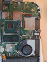
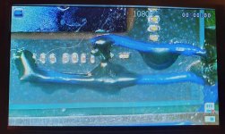
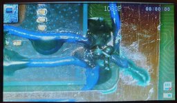
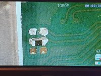
Tried the ram reball, still nothing. Heres some pics i salvaged. The mosfet install looks more messier than it is because i literally doused all connections so its hard to see but check for continuity before masking. check it out. Video is the initial install boot + light pattern. Motherboard pic is with mosfet and pico removed + after reballing attempts. Other two are mosfets. At this point I will wait to invest in a thermal cam + voltage injection tool to find out where exactly the short/problem is. Wether its a cap i missed or a chip thats gone. My uneducated suspicion is the APU has done a Houdini.
The only ways I think PFly installs could be creating BSODs (oops, think my PS4 nightmares took over and I've been typing BLOD XD):
V1\2\Lite - Sloppy MOSFET\flex install, stray solder balls under APU\RAM, knocking parts you don't mean\know, using a high-heat iron for too long on the APU, shorting a weird way and somehow frying the APU (idk, I've abused a lot of Switch boards in my time and have recovered most of them), (V1\2 specific) emmc connector\socket jacked up. No BGA work is needed, so the APU balls should never become questionable, IPA-toothbrush cleaning (try to use a 'blower' on it too) will clear stray balls.
OLEDs are all the same PLUS more risk to emmc through reballing\crap-adaptor, and more risk to APU because CLK isn't for the faint of heart AND is close to the APU. My last BSOD actually WAS an OLED-PFly install, but I've been neglecting posting about it because it's such a 'one off'. That OLED went through hell because I kept chasing my tail on little dumb things and continually 'stepping on my own d'k'. Always 1 step fwd, 2 steps back. It all started with using a crap dat0 adapter though, be warned. So, after messing up and fixing nearly everything, seeing a BSOD meant it could have been ANYTHING (funny though, with how much 'no boot' I was getting, I was EXCITED to see anything on screen, even BSOD). I removed the PZero (being sure hanging wires weren't shorting), did my best emmc reball I'd done yet and it was still BSOD. Grabbed a new PZero to use for troubleshooting, got cyan and thought 'guess I should try a reflow', no change though. Swapped the stupid flex cable (that I'm never buying again, LET HWFLY DIE!) with MOSFETs and I was in Hekate! I restored a backup I had been able to make (seriously? There's MORE to this story? Yikes!) and VOILA! No more BSOD!
TLDR, I fixed a BSOD by successfully restoring a backup in Hekate. Maybe the emmc somehow gets corrupted during installs? And, yes, there's actually plenty more to that story, like how mine was actually a 256gb emmc upgrade XD
Tried the ram reball, still nothing. Heres some pics i salvaged. The mosfet install looks more messier than it is because i literally doused all connections so its hard to see but check for continuity before masking. check it out. Video is the initial install boot + light pattern. Motherboard pic is with mosfet and pico removed + after reballing attempts. Other two are mosfets. At this point I will wait to invest in a thermal cam + voltage injection tool to find out where exactly the short/problem is. Wether its a cap i missed or a chip thats gone. My uneducated suspicion is the APU has done a Houdini.
For the video: 2x long pulses should be a CLK issue.
For the picture: The 7x red circles are concerns and the 2x blue circles are 'eh, should be fine but try not to let unconnected wires lay under motherboards ever'
Red circles from top-down:
1- Missing resistor?
2-4: Lots of mess, hard to be sure what's going on. Recommend trying to get back to factory here.
5. Sign of solder splash\balls? Flux\lighting can throw pics\vids 'off'.
6. Did you pry here? Maybe the caps\traces broke?
Pro tip: use heat to save your liquid damage stickers BEFORE you do work.
The only ways I think PFly installs could be creating BSODs (oops, think my PS4 nightmares took over and I've been typing BLOD XD):
V1\2\Lite - Sloppy MOSFET\flex install, stray solder balls under APU\RAM, knocking parts you don't mean\know, using a high-heat iron for too long on the APU, shorting a weird way and somehow frying the APU (idk, I've abused a lot of Switch boards in my time and have recovered most of them), (V1\2 specific) emmc connector\socket jacked up. No BGA work is needed, so the APU balls should never become questionable, IPA-toothbrush cleaning (try to use a 'blower' on it too) will clear stray balls.
OLEDs are all the same PLUS more risk to emmc through reballing\crap-adaptor, and more risk to APU because CLK isn't for the faint of heart AND is close to the APU. My last BSOD actually WAS an OLED-PFly install, but I've been neglecting posting about it because it's such a 'one off'. That OLED went through hell because I kept chasing my tail on little dumb things and continually 'stepping on my own d'k'. Always 1 step fwd, 2 steps back. It all started with using a crap dat0 adapter though, be warned. So, after messing up and fixing nearly everything, seeing a BSOD meant it could have been ANYTHING (funny though, with how much 'no boot' I was getting, I was EXCITED to see anything on screen, even BSOD). I removed the PZero (being sure hanging wires weren't shorting), did my best emmc reball I'd done yet and it was still BSOD. Grabbed a new PZero to use for troubleshooting, got cyan and thought 'guess I should try a reflow', no change though. Swapped the stupid flex cable (that I'm never buying again, LET HWFLY DIE!) with MOSFETs and I was in Hekate! I restored a backup I had been able to make (seriously? There's MORE to this story? Yikes!) and VOILA! No more BSOD!
TLDR, I fixed a BSOD by successfully restoring a backup in Hekate. Maybe the emmc somehow gets corrupted during installs? And, yes, there's actually plenty more to that story, like how mine was actually a 256gb emmc upgrade XD
Post automatically merged:
I think it was @deeps that was hoping we could add 'press vol+\- for OFW' to the no sd screen. May I request this to be added?
Post automatically merged:
For the video: 2x long pulses should be a CLK issue.
For the picture: The 7x red circles are concerns and the 2x blue circles are 'eh, should be fine but try not to let unconnected wires lay under motherboards ever' View attachment 373173
Red circles from top-down:
1- Missing resistor?
2-4: Lots of mess, hard to be sure what's going on. Recommend trying to get back to factory here.
5. Sign of solder splash\balls? Flux\lighting can throw pics\vids 'off'.
6. Did you pry here? Maybe the caps\traces broke?
Pro tip: use heat to save your liquid damage stickers BEFORE you do work.
Appreciate the unexpected feedback, very grateful to you for taking the time out of your day. 2-4 (apu caps) Looks messier than it is because it was initially covered/protected in solder mask. At this point I have checked all the caps surrounding the APU and they all give continuity.
Checking back on 5, not sure what that is but its not there anymore (might've been fluff from cleaning off residue after reball)
6 Yes, spotted that yesterday, checked the nearby cap for continuity and it was good. Looked deeper at the 'damage' and luckily no traces ran underneath that.
But 1, now that i did not spot before. hmmmm.
will investigate that asap.
thanks again
Edit - I did though download the firmware off of git when it was maybe 8hrs after the release. And maybe it wasn't a good idea as it might have been still in Alpha. And the changelog was - 'v2.72 + disable CLK check, it's unstable'. Just so happens that the pulses were related to CLK. So my question is, is the EMMC dead? Anyway to revive it or is it just gone gone....
I removed it using a soldering iron. And don't ask it is pain in the ass. Add a solder to all four points and start heating it for sec and then move to second. But remove to first upper two points then move to lower points. But I can assure you the port will be remove and buttons as well .But there will be no more pads left. But first check your are using latest firmware.
It will look like this.
Edit: my finger also get a burn a little bit from the port Because I accidentally touched it, it was F hot. But please be carefull. Also, don't laugh at me.
Some cheap hair dryer might have temperature more than normal, you could try to use that.
The working principle is similar. Theres heater near the opening, and the air blows strongly by fan in the back.
Didn't touch the emmc what so ever. And from the picture, yes it looks like....SOMEHOW....SOME WAY....I wasn't careful enough and ripped that, what looks like, 0201 resistor which looks like the trace goes directly under the APU. Potentially have a winner here once I can find the value of that resistor to be replaced. In ohms mode it read at 560ohms but can't be 100% sure. I hope this is it. Thank you because this gives me hope that my soldering and mosfet work was good.
Edit - Anyone know a good resource as to where to find a breakdown/diagram of switch caps/resistor values. Googling it for a while feels like taking a pedal-bike on a motorway, getting nowhere fast.
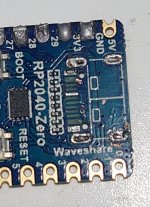
hello guys, I bought a RP2040-Zero and I can't program it, when I connect it to the PC via USB it shows red, green and blue and the PC doesn't see them..
hello guys, I bought a RP2040-Zero and I can't program it, when I connect it to the PC via USB it shows red, green and blue and the PC doesn't see them..
A new Nintendo Switch firmware update is here. System software version 18.0.1 has been released. This update offers the typical stability features as all other...
While rumors had been floating about rampantly as to the future plans of Nintendo, the President of the company, Shuntaro Furukawa, made a brief statement confirming...
As each year passes, retro games become harder and harder to play, as the physical media begins to fall apart and becomes more difficult and expensive to obtain. The...
TheFlow has done it again--a new kernel exploit has been released for PlayStation 4 consoles. This latest exploit is called PPPwn, and works on PlayStation 4 systems...
Nintendo might just as well be a law firm more than a videogame company at this point in time, since they have yet again issued their now almost trademarked usual...
Nintendo has officially announced that a successor to the beloved Switch console is on the horizon. As we eagerly anticipate what innovations this new device will...
Another video game prototype has been found and preserved, and this time, it's none other than the game that spawned an entire franchise beloved by many, the very...
Anbernic is back with yet another retro handheld device. The upcoming RG28XX is another console sporting the quad-core H700 chip of the company's recent RG35XX 2024...
DOOM is well-known for being ported to basically every device with some kind of input, and that list now includes the old retro game console in Persona 5 Royal...
Two classic titles join the Nintendo Switch Online Expansion Pack game lineup. Available starting April 24th will be the motorcycle racing game Extreme G and another...
Nintendo has officially announced that a successor to the beloved Switch console is on the horizon. As we eagerly anticipate what innovations this new device will...
While rumors had been floating about rampantly as to the future plans of Nintendo, the President of the company, Shuntaro Furukawa, made a brief statement confirming...
Nintendo might just as well be a law firm more than a videogame company at this point in time, since they have yet again issued their now almost trademarked usual...
As each year passes, retro games become harder and harder to play, as the physical media begins to fall apart and becomes more difficult and expensive to obtain. The...
A new Nintendo Switch firmware update is here. System software version 18.0.1 has been released. This update offers the typical stability features as all other...
TheFlow has done it again--a new kernel exploit has been released for PlayStation 4 consoles. This latest exploit is called PPPwn, and works on PlayStation 4 systems...
Ubisoft has today officially revealed the next installment in the Assassin's Creed franchise: Assassin's Creed Shadows. This entry is set in late Sengoku-era Japan...
After rumour got out about an upcoming NES Edition release for the famed Nintendo World Championships, Nintendo has officially unveiled the new game, titled "Nintendo...
DOOM is well-known for being ported to basically every device with some kind of input, and that list now includes the old retro game console in Persona 5 Royal...
The number of layoffs and cuts in the videogame industry sadly continue to grow, with the latest huge layoffs coming from Microsoft, due to what MIcrosoft calls a...
Technically for a month there I had Frontier FIOS 500Mbps and Spectrum 1Gbps (they got me on Spectrum because it was a little cheaper for double the speed)
I mean what would you really need that fast for tho, 500mb streams 4k fine. 1gb should be fine for 8k eventually. That's what I just switched to Spermrum.