then there was a issue with ur solderingHappened in a lite with me....really dont know what causes it
if gave 5xlites,10x V1/v2,6 xOleds and never had ANY Issue with a install
then there was a issue with ur solderingHappened in a lite with me....really dont know what causes it
Maybe was that but i think it was one of my best installs i made...i removed the chip and wires and theres the bsod... i think i will try to load hekate and see if the emmc is fine..then there was a issue with ur soldering
if gave 5xlites,10x V1/v2,6 xOleds and never had ANY Issue with a install
Actually the only thing diferent i did was solderint the clk point in the alternate point...because its very close to the cmd point there next to emmcMaybe was that but i think it was one of my best installs i made...i removed the chip and wires and theres the bsod... i think i will try to load hekate and see if the emmc is fine..

That should be 47k 0201 resistor and they don't like the heat very much
You must change that resistorSo I was able to get the switch reassembled without the picofly installed but it still does not power up. I do not see any bridged solder connections anywhere everything looks right. The cap that was knocked off was reinstalled.
Pressing the power button result in no activity no fans spin up
Probably not u would have more luck in smartphonesCan i find resistors 0201 in a pc mother board? I need the ones near the rst point onde switch lite
Hello, I am trying to place the picofly in my oled switch, I have an error in the clk or the CMD, the leds are really very similar. The detail is that if I measure the clk with the multimeter it gives me a value of approx 600kohm and if I measure the CMD it gives me a value of approx 600kohm, the measurements were made without any cable, are these values ok? What do you recommend I do to make the picofly work on my oled switch? I'm using the 2.67 firmware.Latest firmware here
ChangeLog:
v2.0 + Active MMC communication
v2.1 + Toshiba support
v2.2 + Fix Toshiba boot fail
v2.3 + SanDisk support
v2.4 + Faster Toshiba boot
v2.5 + fix OFW boot
v2.6 + software update, xiao & itsy support
v2.61 + Instinct-NX sdloader, bug fixes
v2.62 + Make 16.0.1 happy (fix OFW boot)
v2.63 + roll back some 2.62 boot speed tricks
v2.64 + enable back the board detection
v2.65 + RP Pico support, double reset removed
v2.66 + Bypass to OFW after update for proper fuse burning
v2.67 + Don't bypass to OFW on first install
v2.70 + new LED indication, i2c undervoltage hack
v2.71 + support for SQc open-source board
v2.72 + disable CLK check, it's unstable
v2.73 + add LED signal on success
= is long pulse, * is short pulse:
= USB flashing done
** RST is not connected
*= CMD is not connected
=* D0 is not connected
== CLK is not connected
*** No eMMC CMD1 responce (bad eMMC?)
**= No eMMC block 1 read (should not happen)
*=* No eMMC block 0 read (eMMC init failure?)
*== No eMMC CMD1 request (poor wiring, or dead CPU)
=** eMMC init failure during glitch process
=*= CPU never reach BCT check, should not happen
==* CPU always reach BCT check (no glitch reaction, check mosfet)
=== Glitch attempt limit reached, cannot glitch
=*** eMMC init failure
=**= eMMC write failure - comparison failed
=*=* eMMC write failure - write failed
=*== eMMC test failure - read failed
==** eMMC read failed during firmware update
==*= BCT copy failed - write failure
===* BCT copy failed - comparison failure
==== BCT copy failed - read failure
If your glitch is unstable (==* error), and the proper boot happens only when you press Reset after joycon logo, you can add two more wires to make glitch much better.
board pins:
Waveshare rp2040: SDA=12, SCL=13
Pi Pico: SDA = 19, SCL = 20
XIAO 2040: SDA=3, SCL=4
ItsyBitsy 2040: SDA = 18, SCL = 19
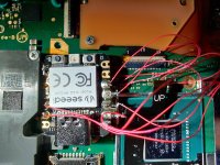
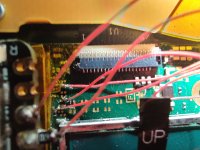
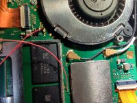
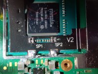
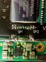
NS points (v2, Lite, OLED):
View attachment 372191
View attachment 372192
View attachment 372193
Q: What is supported?
A: Erista (v1), Mariko (v2, Lite, OLED)
Q: eMMC types support?
A: Tested on Hynix, Samsung, Toshiba, SanDisk
Q: rp2040 boards support
A: WaveShare 2040-zero/one, xiao-rp2040, adafruit itsybitsy (Pi Pico is not supported for now)
Q: GREEN, but instant reset
A: Clean flux near the RST point
Q: Do I really need 47 Ohm resistors?
A: You can skip them, however in this case you will have to use emuMMC due to the line interference, sysNAND would not boot (sysNAND data can be damaged).
Q: Does the firmware has learning? How to reset statistics
A: Short pin 0 to either 1 or GND during start for chip reset. The statistics is collected each boot. The more you start it - the better it boots.
Q: open source?
A: https://github.com/rehius
Q: why you made it?
A: to prove it possible!
Q: run Atmosphere?
A: no piracy
v2.5 firmware had a bug with BOOT0 corruption. To recover it:
- boot "Full Stock" using hekate
- update to the latest official firmware over Wi-Fi
- boot "Full Stock" using hekate
- perform a full system reset
- show firmware information
- update firmware from SD card (place update.bin into the root folder)
- rollback to the backup firmware slot
- reset learning statistics
- dump / write sdloader
if you have an rp2040-zero from waveshare/ali then it has a neopixel. It is used for diagnosing proper firmware flashes as well as console glitching. If you plug it in, and flash the uf2 firmware to it and immediately see a red light after flashing (this is not the same as flashing, then unplugging and replugging), then no rgb jumper needs to be made. If on the other hand, you get one quick green flashing light, then you need to bridge the jumper pads indicated to swap the LED colors for proper diagnoses capability.

SOLVED - THX @abal1000xSeems issue with the voltage. When the logo shows up especially the joycon logo, the voltage of the cap inside the apu (which connected to the mosfet) will be decreased, from around 2V, to around 1V then stopped at 0.643V.
Do you use mosfets or hwfly flex cable?
This has me questioning myself now. https://gbatemp.net/threads/picofly-a-hwfly-switch-modchip.622701/post-10160786
Been reading far back trying to catch up to the current times. I am gathering the parts to install this PicoFly so am just playing with flashing the PicoFly firmware.
Current PicoFlyGuide v6.1 Doesn't says the statement quoted above. I says the following (I assume is this was one of the changes):
"
If the LED flashes Yellow once, GREAT, you don't need to
do anything special, however, if you get multiple flashes,
or no flash at all, the flash was unsuccessful and you
need to attempt flashing the firmware once again.
You can hold the boot button, plug your RP2040-Zero back
into your computer, flash the .uf2 to the board again and
look for a Yellow LED flash now."
I attached a small video link of what I did. If you guys be so kind to let me know if I done it correctly or If I need to bridge the RGB jumper. TIA
Already modded a v2 mariko. Just picked up a lite from Craigslist for my next attempt. Any tips for placing the pico in the shell? Another question, can I use a sad that was already set up on the other switch and boot strait to atmos?
for first time boot its opened automatically so no need to press anything just plug like normal usb flashdrive, if you want to reflash then need to press boot otherwise nothing openedThe correct way to turn the rp2040 into usb mode is by pressing the boot button then power it on the usb. (CMIIW)
In the first development of the firmware, the diagnostic code are coded by color. Rp2040-zero have 2 kind of type of led in the market. One is RGB and the other is GRB something like that. So the color code is green according to the normal one, become red to the others. That is why there is bridge, so for GRB, the color code will be shifted so the color remains the same.
But..... It is now deprecated.
Color is ambigue, cyan and blue is similar, lot of people misunderstand the color. Also theres only 7 distinguished color, so its difficult to diagnostic lot of condition. Then the diagnostic code change from color to pulse (like morse code), in the new firmware.
BTW, in your video, its the normal rp2040-zero. The first color is blue. Its already correct. (CMIIW)
Reference:
* The code that throws blue in the first time picofly boot
https://github.com/rehius/usk/blob/7160263347b5f6e2abdcc2b84905336e4886b4d5/main.c#L105
This has me questioning myself now. https://gbatemp.net/threads/picofly-a-hwfly-switch-modchip.622701/post-10160786
Been reading far back trying to catch up to the current times. I am gathering the parts to install this PicoFly so am just playing with flashing the PicoFly firmware.
Current PicoFlyGuide v6.1 Doesn't says the statement quoted above. I says the following (I assume is this was one of the changes):
"
If the LED flashes Yellow once, GREAT, you don't need to
do anything special, however, if you get multiple flashes,
or no flash at all, the flash was unsuccessful and you
need to attempt flashing the firmware once again.
You can hold the boot button, plug your RP2040-Zero back
into your computer, flash the .uf2 to the board again and
look for a Yellow LED flash now."
I attached a small video link of what I did. If you guys be so kind to let me know if I done it correctly or If I need to bridge the RGB jumper. TIA
Yes i do know that.for first time boot its opened automatically so no need to press anything just plug like normal usb flashdrive, if you want to reflash then need to press boot otherwise nothing opened
This is not Short Circuit right?Hi people!
I have to do the installation by myself because no technician want to help me with.
I don't have experience with soldering, so, begin well.
I'm having ==* that means CPU always reach BCT check.
Here the pics of my installation.
If i disconect the 3.3 point and ground, does nothing, just black screen.
I've backed up all four of the switches that I have modded. I actually just boot fresh factory reset firmware, make my nand/boot0/boot1 backups, dump the keys, and then copy the entire SD card contents to a safe place. After that, I make my emunand, and continue setting up the console.Does anyone can suggest best practice to back up files in hekate after picofly instals, what to back up? nand , keys or etc.
so far ive been neglecting backing up nand due to time, size out of convenience (im talking about if you jailbroken several switches instead of one)
any general thought on this??
To be sold : dont bother. Using it your self : take your time.Does anyone can suggest best practice to back up files in hekate after picofly instals, what to back up? nand , keys or etc.
so far ive been neglecting backing up nand due to time, size out of convenience (im talking about if you jailbroken several switches instead of one)
any general thought on this??
I check it and resolder, and the same result.