


Hi everyone,
I had decided to install the Instinct NX on my OLED Switch and I managed to connect all points besides B properly and now the Switch is unresponsive (won't boot).
For some extra context, I went with the "no reflow" approach to the flex cable meant for the EMMC chip.
The multimeter shows good values for all of the soldered points except the B/RST one (it should be 2.9V from what I've read online but for me it's 0).
I figured that the B point shorted with the ground ring around it (absolutely not sure if it's is for passthrough of the capacitor next to the B point or ground as I couldn't find too much info online).
Despite trying so hard with flux, various temperatures and even trying to use lower temp solder to make cleanup easier on that point, there's always a silver layer on it (unlike others which have a ring).
Does anyone know what my options here are?
Because all I can think of is:
a) stopping the trace which shorted with the B point and then rewiring the transistor to the distanced point (after exposing it with a dremel/engraving tool) it's meant to reach, but that's pretty invasive and I'd like to do that only after I definitely know how exactly that section of the board is supposed to be connected here (because all I can do now is speculate) and only if I have no other option.
b) Trying to carefully sand off the silver layer(solder?) Until the point and ring are perfectly exposed and separated, applying solder mask, curing it, exposing just the middle part of the point and soldering on it.
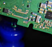
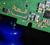
I've attached a photo (the microscope I have has a horrible pic quality so this was the clearest one I could snap) of the board along with a mark-up of the "a" idea (red lines for a trace cut and blue line for rewire - but that's just me guessing that's how it's supposed to go...).
In conclusion, I'd like to ask if my thinking process regarding the available options is okay (with the way I think the connections are supposed to be like) and if there's a better way to resolve this issue.
Any kind of help/ would be greatly appreciated.
I had decided to install the Instinct NX on my OLED Switch and I managed to connect all points besides B properly and now the Switch is unresponsive (won't boot).
For some extra context, I went with the "no reflow" approach to the flex cable meant for the EMMC chip.
The multimeter shows good values for all of the soldered points except the B/RST one (it should be 2.9V from what I've read online but for me it's 0).
I figured that the B point shorted with the ground ring around it (absolutely not sure if it's is for passthrough of the capacitor next to the B point or ground as I couldn't find too much info online).
Despite trying so hard with flux, various temperatures and even trying to use lower temp solder to make cleanup easier on that point, there's always a silver layer on it (unlike others which have a ring).
Does anyone know what my options here are?
Because all I can think of is:
a) stopping the trace which shorted with the B point and then rewiring the transistor to the distanced point (after exposing it with a dremel/engraving tool) it's meant to reach, but that's pretty invasive and I'd like to do that only after I definitely know how exactly that section of the board is supposed to be connected here (because all I can do now is speculate) and only if I have no other option.
b) Trying to carefully sand off the silver layer(solder?) Until the point and ring are perfectly exposed and separated, applying solder mask, curing it, exposing just the middle part of the point and soldering on it.
I've attached a photo (the microscope I have has a horrible pic quality so this was the clearest one I could snap) of the board along with a mark-up of the "a" idea (red lines for a trace cut and blue line for rewire - but that's just me guessing that's how it's supposed to go...).
In conclusion, I'd like to ask if my thinking process regarding the available options is okay (with the way I think the connections are supposed to be like) and if there's a better way to resolve this issue.
Any kind of help/ would be greatly appreciated.
Attachments
Last edited by Jeik,


