


Recently I uncover a old PlayStation 1 mpeg console in my storeroom. It use DC 9v. Behind the VCD console got AV out and P/S connector. Upon connect the AV cable to TV and switching to VCD mode , a display of winbond image display and prove it still work. However I lost the P/S cable which suppose to connect to the PlayStation 1 console. I remember when I was young , this vcd console will enable VCD mode to play VCD from PS1 fat console. However I forgotten what kind of P/S cable it use as I lost it. Anybody in the forum know where to get this kind of cable or do this type of cable still exist to buy?
You are using an out of date browser. It may not display this or other websites correctly.
You should upgrade or use an alternative browser.
You should upgrade or use an alternative browser.
Help identify P/S cable for Old rare PS1 mpeg converter
- Thread starter philipx99
- Start date
- Views 1,742
- Replies 16


It's not likely to help much, but:
7 pin mini-DIN (key in the center)
https://connector.pinouts.ru/7_pin_mini-DIN_female_key_in_the_center/
pinout is obviously differs depending on the device
7 pin mini-DIN (key in the center)
https://connector.pinouts.ru/7_pin_mini-DIN_female_key_in_the_center/
pinout is obviously differs depending on the device

I was thinking is there any cable that have one end 7 pin mini din male connector and then the other end is PlayStation video connector. Is there such a cable?It's not likely to help much, but:
7 pin mini-DIN (key in the center)
https://connector.pinouts.ru/7_pin_mini-DIN_female_key_in_the_center/
pinout is obviously differs depending on the device
- Joined
- Sep 13, 2022
- Messages
- 7,244
- Trophies
- 3
- Location
- The Wired
- Website
- m4x1mumrez87.neocities.org
- XP
- 22,220
- Country


You'll have to either make your own cable, or source one from someone, or the company who manufactured them (slim chances of finding them).I was thinking is there any cable that have one end 7 pin mini din male connector and then the other end is PlayStation video connector. Is there such a cable?
The trouble with the mini din 7 pin connector, is that not every company will adhere to the standard -if one does exists-. For example, they could have mapped the standard composite signal to a completely different pin than what the standard specifies.
- Joined
- Sep 6, 2013
- Messages
- 3,198
- Trophies
- 2
- Location
- Bullet Hell
- Website
- www.exophase.com
- XP
- 4,310
- Country
I imagine it would be a proprietory cable with 7-pin mini din on one end and an edge connector (to the PS's serial port) on the other.
I had a vcd player/module for the PS1 back in the days, mine plugged into the expansion slot in the back. But didn't have that DIN
socket, wonder if there's another piece to this hardware that plugs into the expansion slot? I remember it also plugged into the AV port for video passthrough.
socket, wonder if there's another piece to this hardware that plugs into the expansion slot? I remember it also plugged into the AV port for video passthrough.
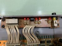
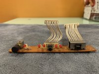
Judging by the switch on the front panel there is most likely both S-Video and stereo audio in the same cable/plug.
The pinout is of course proprietary (of their own invention). And I wouldn't be surprised if the plugs themselves had components like resistors inside.
It's worth looking for the owner of exactly the same device but with a cable and who is able to measure connections of the cable and compute a pinout scheme.
Or to study the inner workings of the device board. A kind of reverse-engineering.
And to DIY such a cable.
As above if you can find someone with such a cable and get them to bell it out (possibly resistance as well if we think that is going to be a thing) and take some pictures (knowing what the PS1 side of things was would help narrow down uses) that would be nice, though how many of those or similar enough model still exist I do not know.
Most VCD things I saw back when were not external devices (give or take the basic homebrew enabling cheat cartridges but they are functionally just a mod chip for these purposes) though so I am not sure what goes for this, or what particular function either the device serves or the PS1 serves unless it is just a CD player passthrough in this with all the smarts in the box. That said VCD was far more of a thing in Asia (your flag does say Singapore*) so there is that to consider as well, and if it was around the time then standalone CDs might have been rare just as people used PS2s as DVD players a few years later, and PS3 blu ray beyond that.
I don't think it would be any kind of overlay type device (subtitles and such) at that point.
*I saw I think it was an Indonesian PS1 video out the other day at a car boot sale. Had two prongs on the thing which I had never seen. Probably should have picked it up for the shelf of weird things but hey.
The PS1 has two output options
https://psx-spx.consoledev.net/expansionportpio/
https://psx-spx.consoledev.net/serialportsio/
Plus controller, memory card and whatnot.
Serial port is likely to be too slow to do much in the way of CD reads, though at the same time if the PS1 was 2x CD that is maybe 300 kilobytes a second and thus back in the region of it, not to mention VCD bitrates are 1150 kbits (divide by 8 to get bytes) then still under the limit.
Unless it was serial port mod chip as it were and had some kind of controller built into it.
7 pin socket (8 if you include shielding which is just another ground) does hint towards https://problemkaputt.de/psx-spx.htm#pinoutssiopinouts rather than expansion (many more pins, though as not all pins are used by all things then not flawless, though here as most of the big stuff is 16 pins and 24 pins less likely, scroll up a bit on the link above for a pinout). It is serial so mostly going to be TX (transmit), RX (receive, remember to reverse TX and RX between the devices as what transmits from one is received by the other and vice versa), voltage, ground, clear to send which you can probably determine easily enough by following traces from whatever chip it comes from inside the box (assuming you can find a pin out of that or play with an oscilloscope).
Probably not going to be RS232 (what most think of if you say serial port) but the principles he uses to reverse engineer it and in some related videos of that little series are pretty much identical to what you would want to do in the absence of an existing cable to bell out.
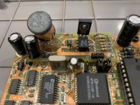
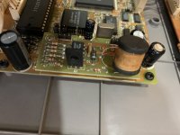
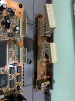
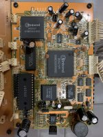
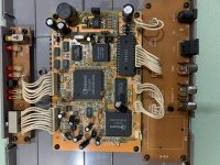
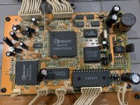
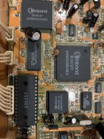
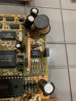
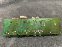
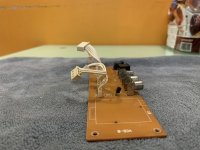
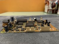
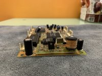
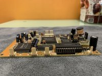
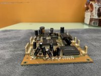
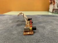
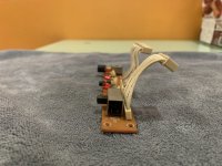
Hereby is some more image of the gut of the mpeg converter. I can’t really recall whether do it need any other accessories to connect or do it connect to the serial port or expansion port. But I can remember it use for playing VCD video format at that time. Hope someone who have use the same converter to share their view on what 7 pin s video cable use.
Attachments
-
 IMG_1061.jpeg1.3 MB · Views: 35
 -
 IMG_1064.jpeg1.2 MB · Views: 28
 -
 IMG_1065.jpeg1.2 MB · Views: 28
 -
 IMG_1066.jpeg3.5 MB · Views: 22
 -
 IMG_1067.jpeg1.8 MB · Views: 26
 -
 IMG_1046.jpeg1.1 MB · Views: 23
 -
 IMG_1060.jpeg1.8 MB · Views: 27
 -
 IMG_1059.jpeg1.1 MB · Views: 21
 -
 IMG_1058.jpeg2.1 MB · Views: 26
 -
 IMG_1049.jpeg3.4 MB · Views: 24
 -
 IMG_1050.jpeg3.4 MB · Views: 24
 -
 IMG_1051.jpeg3.2 MB · Views: 20
 -
 IMG_1052.jpeg2.5 MB · Views: 18
 -
 IMG_1053.jpeg2.3 MB · Views: 26
 -
 IMG_1057.jpeg1.7 MB · Views: 25
Last edited by philipx99,
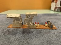
Nice pictures. Any chance we can get an underside shot of the connectors board (looks like just the 4 screws)? Mostly for the connector so we can try to further guess (though I imagine the 7 wire is that connector is going to that, the others being obviously power on the far side and the probably video and audio split for the others. Sadly I don't think the screen printing next to the 7 pin connector/larger header is going to be much use either despite first glance being hopeful.
I am curious about the unpopulated RF part as well, though that is probably just an RF out that was on some models or regions (the size is about the size of the shielded things I would see in a VCR). The CD port (missing a header as well, unlike the RF) also has me curious.
Don't like some of the flaking/corrosion on the connectors either.
- Joined
- Sep 13, 2022
- Messages
- 7,244
- Trophies
- 3
- Location
- The Wired
- Website
- m4x1mumrez87.neocities.org
- XP
- 22,220
- Country
If you're willing to understand as to where the connections are leading to, then it would be also best to take photos of each side of the PCB, load them into your favourite photo editing program and highlight the traces with the pen tool, this will make finding out the connections really easier. I also recommend using a multimeter to test the continuity.
Will try to get more image on the underside of the board once I back home.Nice pictures. Any chance we can get an underside shot of the connectors board (looks like just the 4 screws)? Mostly for the connector so we can try to further guess (though I imagine the 7 wire is that connector is going to that, the others being obviously power on the far side and the probably video and audio split for the others. Sadly I don't think the screen printing next to the 7 pin connector/larger header is going to be much use either despite first glance being hopeful.
I am curious about the unpopulated RF part as well, though that is probably just an RF out that was on some models or regions (the size is about the size of the shielded things I would see in a VCR). The CD port (missing a header as well, unlike the RF) also has me curious.
Don't like some of the flaking/corrosion on the connectors either.
Post automatically merged:
Unfortunately I not very good at circuitry tracing and use of editing software. Regards.If you're willing to understand as to where the connections are leading to, then it would be also best to take photos of each side of the PCB, load them into your favourite photo editing program and highlight the traces with the pen tool, this will make finding out the connections really easier. I also recommend using a multimeter to test the continuity.
Post automatically merged:
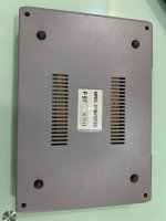
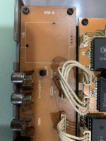
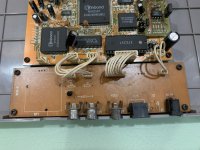
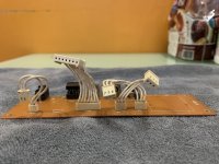
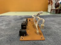
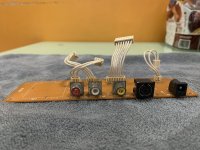
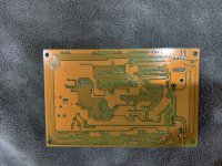
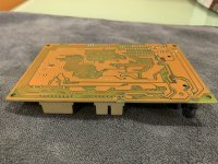
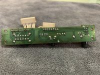
Hereby image of the underside and side of the board. Thank everyone for the assist. Regards.
Attachments
-
 IMG_1079.jpeg4 MB · Views: 39
 -
 IMG_1080.jpeg3.3 MB · Views: 21
 -
 IMG_1081.jpeg3.2 MB · Views: 20
 -
 IMG_1082.jpeg3.3 MB · Views: 22
 -
 IMG_1083.jpeg3.3 MB · Views: 20
 -
 IMG_1084.jpeg3.3 MB · Views: 27
 -
 IMG_1085.jpeg3.5 MB · Views: 20
 -
 IMG_1086.jpeg3.5 MB · Views: 28
 -
 IMG_1087.jpeg3.1 MB · Views: 25
 -
 IMG_1089.jpeg5 MB · Views: 24
 -
 IMG_1090.jpeg3.7 MB · Views: 29
 -
 IMG_1091.jpeg3.2 MB · Views: 25
 -
 IMG_1092.jpeg3.1 MB · Views: 23
 -
 IMG_1093.jpeg3.2 MB · Views: 25
 -
 IMG_1094.jpeg3.2 MB · Views: 26
 -
 IMG_1095.jpeg3.8 MB · Views: 30
Last edited by philipx99,
- Joined
- Sep 13, 2022
- Messages
- 7,244
- Trophies
- 3
- Location
- The Wired
- Website
- m4x1mumrez87.neocities.org
- XP
- 22,220
- Country
Thanks. This will definitely come in handy.Will try to get more image on the underside of the board once I back home.
Post automatically merged:
Unfortunately I not very good at circuitry tracing and use of editing software. Regards.
Post automatically merged:
Hereby image of the underside and side of the board. Thank everyone for the assist. Regards.
UPDATE #1: Okay. This looks more like an S-Video port to me.
(Attached are summary documents for the main processing chips.)
Attachments
Last edited by SylverReZ,
Sorry, caught out by the merger. Seems like some nice 90s auto router done for this one.
My dry joint alarm is going off for
https://gbatemp.net/attachments/img_1079-jpeg.366577/
Not to mention the creeping oxidation under the mask would have me concerned. Top right pin in that short of the unknown lead/lead we are concerned with. Few spots on what looks like the ground plane on the far right. No connections to other video things I can easily see but could well be isolation if good design or said 90s auto router.
The shield looks connected to another pin which goes to pin 4/middle pin so presumably a ground. Will have to compare against what I can see about chips.
I guess hope that someone who have use this before share their thought or post their type of cable.Thanks. This will definitely come in handy.
UPDATE #1: Okay. This looks more like an S-Video port to me.
(Attached are summary documents for the main processing chips.)
Similar threads
- Replies
- 0
- Views
- 877
- Replies
- 0
- Views
- 632
- Replies
- 3
- Views
- 886
- Replies
- 2
- Views
- 2K
- Replies
- 9
- Views
- 3K
Site & Scene News
New Hot Discussed
-
-
24K views
Wii U and 3DS online services shutting down today, but Pretendo is here to save the day
Today, April 8th, 2024, at 4PM PT, marks the day in which Nintendo permanently ends support for both the 3DS and the Wii U online services, which include co-op play...by ShadowOne333 179 -
20K views
Nintendo Switch firmware update 18.0.1 has been released
A new Nintendo Switch firmware update is here. System software version 18.0.1 has been released. This update offers the typical stability features as all other... -
17K views
The first retro emulator hits Apple's App Store, but you should probably avoid it
With Apple having recently updated their guidelines for the App Store, iOS users have been left to speculate on specific wording and whether retro emulators as we... -
17K views
Delta emulator now available on the App Store for iOS
The time has finally come, and after many, many years (if not decades) of Apple users having to side load emulator apps into their iOS devices through unofficial...by ShadowOne333 96 -
14K views
TheFloW releases new PPPwn kernel exploit for PS4, works on firmware 11.00
TheFlow has done it again--a new kernel exploit has been released for PlayStation 4 consoles. This latest exploit is called PPPwn, and works on PlayStation 4 systems... -
13K views
Nintendo takes down Gmod content from Steam's Workshop
Nintendo might just as well be a law firm more than a videogame company at this point in time, since they have yet again issued their now almost trademarked usual...by ShadowOne333 113 -
11K views
A prototype of the original "The Legend of Zelda" for NES has been found and preserved
Another video game prototype has been found and preserved, and this time, it's none other than the game that spawned an entire franchise beloved by many, the very...by ShadowOne333 31 -
10K views
Anbernic reveals specs details of pocket-sized RG28XX retro handheld
Anbernic is back with yet another retro handheld device. The upcoming RG28XX is another console sporting the quad-core H700 chip of the company's recent RG35XX 2024... -
10K views
Nintendo "Indie World" stream announced for April 17th, 2024
Nintendo has recently announced through their social media accounts that a new Indie World stream will be airing tomorrow, scheduled for April 17th, 2024 at 7 a.m. PT...by ShadowOne333 53 -
9K views
Nintendo Switch Online adds two more Nintendo 64 titles to its classic library
Two classic titles join the Nintendo Switch Online Expansion Pack game lineup. Available starting April 24th will be the motorcycle racing game Extreme G and another...
-
-
-
179 replies
Wii U and 3DS online services shutting down today, but Pretendo is here to save the day
Today, April 8th, 2024, at 4PM PT, marks the day in which Nintendo permanently ends support for both the 3DS and the Wii U online services, which include co-op play...by ShadowOne333 -
113 replies
Nintendo takes down Gmod content from Steam's Workshop
Nintendo might just as well be a law firm more than a videogame company at this point in time, since they have yet again issued their now almost trademarked usual...by ShadowOne333 -
97 replies
The first retro emulator hits Apple's App Store, but you should probably avoid it
With Apple having recently updated their guidelines for the App Store, iOS users have been left to speculate on specific wording and whether retro emulators as we...by Scarlet -
96 replies
Delta emulator now available on the App Store for iOS
The time has finally come, and after many, many years (if not decades) of Apple users having to side load emulator apps into their iOS devices through unofficial...by ShadowOne333 -
79 replies
Nintendo Switch firmware update 18.0.1 has been released
A new Nintendo Switch firmware update is here. System software version 18.0.1 has been released. This update offers the typical stability features as all other...by Chary -
77 replies
TheFloW releases new PPPwn kernel exploit for PS4, works on firmware 11.00
TheFlow has done it again--a new kernel exploit has been released for PlayStation 4 consoles. This latest exploit is called PPPwn, and works on PlayStation 4 systems...by Chary -
55 replies
Nintendo Switch Online adds two more Nintendo 64 titles to its classic library
Two classic titles join the Nintendo Switch Online Expansion Pack game lineup. Available starting April 24th will be the motorcycle racing game Extreme G and another...by Chary -
53 replies
Nintendo "Indie World" stream announced for April 17th, 2024
Nintendo has recently announced through their social media accounts that a new Indie World stream will be airing tomorrow, scheduled for April 17th, 2024 at 7 a.m. PT...by ShadowOne333 -
52 replies
The FCC has voted to restore net neutrality, reversing ruling from 2017
In 2017, the United States Federal Communications Commission (FCC) repealed net neutrality. At the time, it was a major controversy between internet service providers...by Chary -
43 replies
AYANEO officially launches the Pocket S, its next-generation Android gaming handheld
Earlier this year, AYANEO revealed details of its next Android-based gaming handheld, the AYANEO Pocket S. However, the actual launch of the device was unknown; that...by Prans
-
Popular threads in this forum
General chit-chat
-
 BakerMan
Loading…I rather enjoy a life of taking it easy. I haven't reached that life yet though.
BakerMan
Loading…I rather enjoy a life of taking it easy. I haven't reached that life yet though.
-
 @
BigOnYa:
@Psionic Roshambo You lucky they coming to install on a Sunday...Or that they didn't say "They will be there sometime between Sunday 12pm to Saturday 12am." Lol+1
@
BigOnYa:
@Psionic Roshambo You lucky they coming to install on a Sunday...Or that they didn't say "They will be there sometime between Sunday 12pm to Saturday 12am." Lol+1 -
 @
The Real Jdbye:
@Psionic Roshambo time to get really into private trackers so you can make full use of it+1
@
The Real Jdbye:
@Psionic Roshambo time to get really into private trackers so you can make full use of it+1 -
-
-
-
-
-
-
-
-
-
-
-
-
-
 @
K3Nv2:
https://youtu.be/j3OhV1och50?si=7RFGXMYCwKgKIZ5G the drake and Kendrick love story continues
@
K3Nv2:
https://youtu.be/j3OhV1och50?si=7RFGXMYCwKgKIZ5G the drake and Kendrick love story continues -
 @
Arne214:
hi guys, i installed some games using the WUP installer and in the settings the drive shows the games, but they are not visible on the Wii U menu. Can someone help? Thanks
@
Arne214:
hi guys, i installed some games using the WUP installer and in the settings the drive shows the games, but they are not visible on the Wii U menu. Can someone help? Thanks -
-
-
-
-
-
-
-