


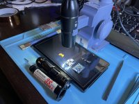
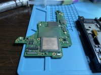
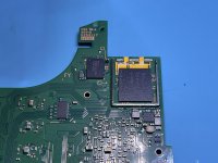
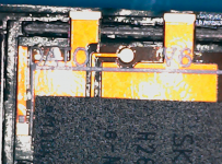
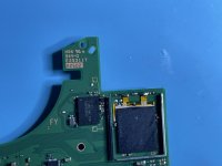
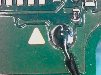
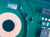
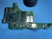
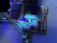
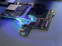
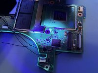
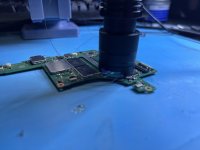
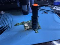
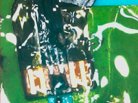
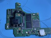
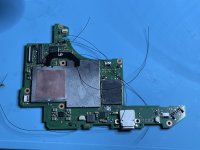
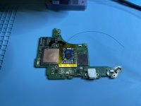
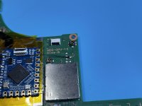
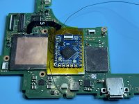
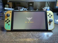
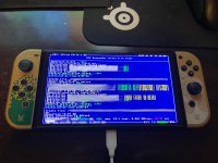
Hey everyone, I'm pretty new around here and to switch modding in general. I just did my first OLED pico install last night I'm so excited but I just don't have anyone to tell about it lol. It was my second mod chip installation on a switch but my first OLED. Everything seems to be in great working order and already have 47 games on it! The installation took 4.5 hours from screws out to screws in and went very smoothly. Probably the most fun project I've done in a while. I just want to share some pics of the process and see if anyone has any critiques on how my solder joints look. All the pictures should be in more or less the order in which I did things. Some connection pics might be missing I think.
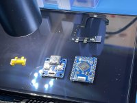
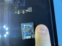
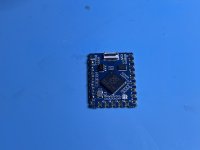
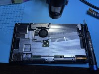
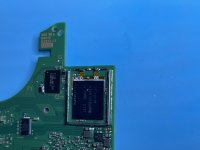
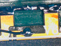
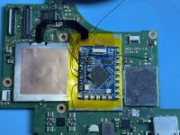
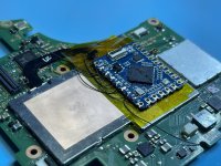
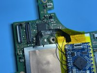
I went the rp2040-tiny route because I didn't want to mess with taking any of the ports/buttons off the chip to make it fit. The chip fits perfectly in the casing with no cutting of the aluminum shielding which was nice. I did however have to adjust where the chip was placed, the wires and chip were a little too close to the cooler, I'll know to install it more to the right side of the shield next time. I also added more solder mask to a few of the connections that had a bit too much wire exposed for my liking (not pictured).
Edit: For anyone wondering the rp2040-tiny I bought from AliExpress and did have the required 47ohm resistors already on the board which made things much easier for the install.
Anyway, I hope it's OK to post this here, please let me know if this should be put in a different part of the forum. Thanks for viewing!
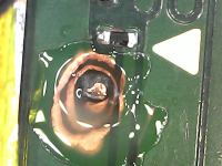
EDIT 10-28-23: After about 20 days the Dat0 shifted somehow and was booting to OFW so I did the top alternate Dat0 mod (drill through the top layers to reach the point) and now it works perfectly!!
I went the rp2040-tiny route because I didn't want to mess with taking any of the ports/buttons off the chip to make it fit. The chip fits perfectly in the casing with no cutting of the aluminum shielding which was nice. I did however have to adjust where the chip was placed, the wires and chip were a little too close to the cooler, I'll know to install it more to the right side of the shield next time. I also added more solder mask to a few of the connections that had a bit too much wire exposed for my liking (not pictured).
Edit: For anyone wondering the rp2040-tiny I bought from AliExpress and did have the required 47ohm resistors already on the board which made things much easier for the install.
Anyway, I hope it's OK to post this here, please let me know if this should be put in a different part of the forum. Thanks for viewing!
EDIT 10-28-23: After about 20 days the Dat0 shifted somehow and was booting to OFW so I did the top alternate Dat0 mod (drill through the top layers to reach the point) and now it works perfectly!!
Attachments
-
 1 - Copy.jpg951.6 KB · Views: 34
 -
 2 - Copy.jpg836.5 KB · Views: 50
 -
 3 - Copy.jpg725 KB · Views: 55
 -
 4 - Copy.jpg767.2 KB · Views: 51
 -
 5 - Copy.jpg664.4 KB · Views: 46
 -
 6 - Copy.jpg1.8 MB · Views: 45
 -
 6-1 - Copy.jpg948.5 KB · Views: 29
 -
 7 - Copy.jpg1.9 MB · Views: 45
 -
 8 - Copy.jpg1.3 MB · Views: 50
 -
 9 - Copy.jpg977.9 KB · Views: 53
 -
 10 - Copy.png1.1 MB · Views: 32
 -
 11 - Copy.jpg827.4 KB · Views: 51
 -
 12 - Copy.jpg768.9 KB · Views: 45
 -
 13 - Copy.png1.2 MB · Views: 33
 -
 14 - Copy.png925.9 KB · Views: 49
 -
 14-1 - Copy.png713.8 KB · Views: 48
 -
 15 - Copy.png7.7 MB · Views: 35
 -
 15-1 - Copy.jpg702.4 KB · Views: 53
 -
 15-2 - Copy.jpg686.2 KB · Views: 52
 -
 15-3 - Copy.jpg708.4 KB · Views: 53
 -
 15-4 - Copy.jpg424.5 KB · Views: 54
 -
 15-5 - Copy.jpg584.7 KB · Views: 55
 -
 16 - Copy.png1 MB · Views: 53
 -
 17 - Copy.jpg1.4 MB · Views: 57
 -
 18 - Copy.jpg1.2 MB · Views: 41
 -
 19 - Copy.jpg1.1 MB · Views: 47
 -
 20 - Copy.jpg725.2 KB · Views: 52
 -
 21 - Copy.jpg1.6 MB · Views: 37
 -
 22 - Copy.jpg1.3 MB · Views: 58
 -
 23 - Copy.jpg909.5 KB · Views: 43
 -
 24 - Copy.jpg1.5 MB · Views: 41
 -
 25 - Copy.jpg901.8 KB · Views: 55
 -
 26 - Copy.jpg1.1 MB · Views: 52
 -
 27 - Copy.jpg1.7 MB · Views: 39
 -
 20231024-224141-322.png872.8 KB · Views: 37
Last edited by Thedoctor22111,

