


Quick question. Theoretically speaking. What would happen if, a modchip was glitching and the power was cut by disconnecting the battery? Would that corrupt the NAND? Theoretically.......hehe...hehe
You are using an out of date browser. It may not display this or other websites correctly.
You should upgrade or use an alternative browser.
You should upgrade or use an alternative browser.
Staff Posts
Recent threadmarks
sharing files
Important Posts
Recent threadmarks
Firmwares- Joined
- Sep 2, 2020
- Messages
- 1,298
- Trophies
- 0
- Age
- 39
- Location
- TORONTO
- Website
- form.jotform.com
- XP
- 2,234
- Country

Very true, I will just patiently wait for the details from himSome mods have nothing to do with practicality, and everything to do with COOL points.

Just completed it, its holiday here.. hahaHi @abal1000x , confirmed for lite .. tested also .. as always with aon mosfet.. now just need to tidy things up. Thanks for the research.
RIP hwfly flex cable.
Thanks for you all here.
Attachments
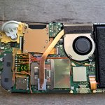

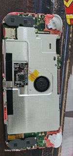
Most caps are there to smooth out any ripples in the power rails.Hi!
I accidentally removed and lost these two caps right now on a zero. (i marked it with yellow.)
what cap is these two?
i need to replace them or i can just leave it be and gonna work like this?
They are there for extra stability so if for some reason everything feels unstable, those missing caps might be the reason.
Since the board is not under heavy load or does not have to power any additional circuitry, I presume you won't notice the difference.
The one on the top near the voltage regulator is at least one of such stabilization caps.
I think it is 1uF according to the schematic on this page :
https://www.digikey.com/en/maker/pr...-1-schematic/c4326f0fd813413698d617cf625125ee
I don't know where the other is connected too.
Most other caps are either 1uF or 0.1 uF.
So just try it and if things are sometimes unstable, just add some capacitor you have at hand.

Most caps are there to smooth out any ripples in the power rails.
They are there for extra stability so if for some reason everything feels unstable, those missing caps might be the reason.
Since the board is not under heavy load or does not have to power any additional circuitry, I presume you won't notice the difference.
The one on the top near the voltage regulator is at least one of such stabilization caps.
I think it is 1uF according to the schematic on this page :
https://www.digikey.com/en/maker/pr...-1-schematic/c4326f0fd813413698d617cf625125ee
I don't know where the other is connected too.
Most other caps are either 1uF or 0.1 uF.
So just try it and if things are sometimes unstable, just add some capacitor you have at hand.
thanks.
so it's not like it's gonna kill the switch or anything?
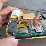
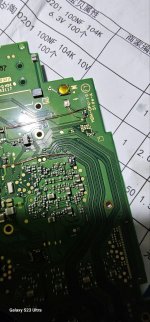
i have a other two that have missing caps near the type c connector and don't have one by default, that caps needed or it's just for the type c connection?
i'm going to rape 2 switch for my little brothers so in the worst case i can sacrifice one to make the other 2 whole.
i can wait 2weeks for my oled, just my lil brats nagging me when i'm gonna mod their switches.
Attachments

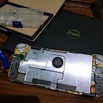
Looks good and CongratsJust completed it, its holiday here.. haha
RIP hwfly flex cable.
Thanks for you all here.
glad u got rid of that hwfly Trash Xd
next time use thinner wires then it looks even better :-)

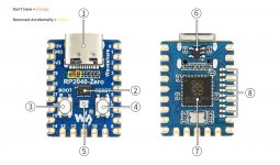
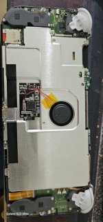
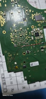
@QuiTim @jkyoho thank you for your patience; here is the diagram for how I attached the status LED to the joy-con PCB. I removed the original home button LED in my installation, though it may be possible to mount the status LED directly next to the original, as the LED used on the RP2040 zero is smaller than the one on my seeed xiao RP2040. I also cut a hole in the rubber membrane between the button and the motherboard, to accommodate the LED and make certain the button could depress properly.

DIN point on the RP2040-Zero:

points to connect the LED DIN line from the RP2040 to the joy-con rail ribbon connector (first is v1/v2, second is oled):


edit: while I have the photoshop file open, here is a diagram for how I wired my lite install as well. this one is far more practical and I have seen a couple other people do it since my first post, so it would be fun to see more home button lights moving forward

DIN point on the RP2040-Zero:
points to connect the LED DIN line from the RP2040 to the joy-con rail ribbon connector (first is v1/v2, second is oled):
edit: while I have the photoshop file open, here is a diagram for how I wired my lite install as well. this one is far more practical and I have seen a couple other people do it since my first post, so it would be fun to see more home button lights moving forward
Last edited by vulp_vibes,
nice thanks for the info just for the fun of it i will probally do it someday@QuiTim @jkyoho thank you for your patience; here is the schematic for how I attached the status LED to the joy-con PCB. I removed the original home button LED in my installation, though it may be possible to mount the status LED directly next to the original, as the LED used on the RP2040 zero is smaller than the one on my seeed xiao RP2040. I also cut a hole in the rubber membrane between the button and the motherboard, to accommodate the LED and make certain the button could depress properly.
View attachment 380935
DIN point on the RP2040-Zero:
View attachment 380940
points to connect the LED DIN line from the RP2040 to the joy-con rail ribbon connector (first is v1/v2, second is oled):
View attachment 380939View attachment 380936
probally get the switch running way faster and with better cooling performance Xd

Single Mosfet IRFHS8342 & NP2016 work fine without SDA/SCL points
let's say goodbye to HWfly flex cable & SDA/SCL points
Thanks for sharing @abal1000x
let's say goodbye to HWfly flex cable & SDA/SCL points
Thanks for sharing @abal1000x
Attachments

So I've gotten this switch modded, hekate boots fine, but...
It no longer boots OFW (volume buttons held down), instead I just get a black screen
SysNAND CFW boot results in the following:

EmuMMC CFW boot results in the following:

The switch has never been modded before, I made a backup immediately after the mod was complete, but it was already in this state by then
Any advice?
It no longer boots OFW (volume buttons held down), instead I just get a black screen
SysNAND CFW boot results in the following:
EmuMMC CFW boot results in the following:
The switch has never been modded before, I made a backup immediately after the mod was complete, but it was already in this state by then
Any advice?

Add resistor on cmd and/or dat0 so the value around 100 ohms.So I've gotten this switch modded, hekate boots fine, but...
It no longer boots OFW (volume buttons held down), instead I just get a black screen
SysNAND CFW boot results in the following:
View attachment 380966
EmuMMC CFW boot results in the following:
View attachment 380967
The switch has never been modded before, I made a backup immediately after the mod was complete, but it was already in this state by then
Any advice?
If existing resistor is 47ohms, people usually add it with another 47ohms.
What is the format of the SD card if it is Exfat change it to fat32.So I've gotten this switch modded, hekate boots fine, but...
It no longer boots OFW (volume buttons held down), instead I just get a black screen
SysNAND CFW boot results in the following:
View attachment 380966
EmuMMC CFW boot results in the following:
View attachment 380967
The switch has never been modded before, I made a backup immediately after the mod was complete, but it was already in this state by then
Any advice?
You could even get some normal capacitors from some other device.thanks.
so it's not like it's gonna kill the switch or anything?
i have a other two that have missing caps near the type c connector and don't have one by default, that caps needed or it's just for the type c connection?
i'm going to rape 2 switch for my little brothers so in the worst case i can sacrifice one to make the other 2 whole.
i can wait 2weeks for my oled, just my lil brats nagging me when i'm gonna mod their switches.
These low value capacitors are everywhere.
Already fat32, thanks for the suggestion though!What is the format of the SD card if it is Exfat change it to fat32.
I'll shorten my wires and give this a shot if that doesn't work. Thanks!Add resistor on cmd and/or dat0 so the value around 100 ohms.
If existing resistor is 47ohms, people usually add it with another 47ohms.

So I've gotten this switch modded, hekate boots fine, but...
It no longer boots OFW (volume buttons held down), instead I just get a black screen
SysNAND CFW boot results in the following:
View attachment 380966
EmuMMC CFW boot results in the following:
View attachment 380967
The switch has never been modded before, I made a backup immediately after the mod was complete, but it was already in this state by then
Any advice?
Remove the SDCard then try too boot into OFW.
If still black screen then you need to clean up clk, cmd solrder point... better to redo also.
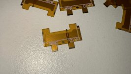
Looks good to me, not the bulky rounded touch point.I’ve just received the “New” DAT0 adapter. They look like the “good” ones, am I right?
github.<remove this space>com<remove this space>/Ansem-SoD/Picofly/tree/main/Firmwares/Archived/2.74Does anyone have the 2.74, it’s so much faster than 2.73 at least in some of my previous installations. I want to install them on newers

Thank you so much for putting all this work in just so we can have a clear idea of how to do this.@QuiTim @jkyoho thank you for your patience; here is the diagram for how I attached the status LED to the joy-con PCB. I removed the original home button LED in my installation, though it may be possible to mount the status LED directly next to the original, as the LED used on the RP2040 zero is smaller than the one on my seeed xiao RP2040. I also cut a hole in the rubber membrane between the button and the motherboard, to accommodate the LED and make certain the button could depress properly.
View attachment 380935
DIN point on the RP2040-Zero:
View attachment 380940
points to connect the LED DIN line from the RP2040 to the joy-con rail ribbon connector (first is v1/v2, second is oled):
View attachment 380939View attachment 380936
edit: while I have the photoshop file open, here is a diagram for how I wired my lite install as well. this one is far more practical and I have seen a couple other people do it since my first post, so it would be fun to see more home button lights moving forward
View attachment 380957
Very much appreciated.
Similar threads
- Replies
- 3
- Views
- 2K
- Replies
- 2
- Views
- 546
- Replies
- 42
- Views
- 6K
Site & Scene News
New Hot Discussed
-
-
29K views
Nintendo Switch firmware update 18.0.1 has been released
A new Nintendo Switch firmware update is here. System software version 18.0.1 has been released. This update offers the typical stability features as all other... -
22K views
Nintendo officially confirms Switch successor console, announces Nintendo Direct for next month
While rumors had been floating about rampantly as to the future plans of Nintendo, the President of the company, Shuntaro Furukawa, made a brief statement confirming... -
22K views
New static recompiler tool N64Recomp aims to seamlessly modernize N64 games
As each year passes, retro games become harder and harder to play, as the physical media begins to fall apart and becomes more difficult and expensive to obtain. The... -
21K views
TheFloW releases new PPPwn kernel exploit for PS4, works on firmware 11.00
TheFlow has done it again--a new kernel exploit has been released for PlayStation 4 consoles. This latest exploit is called PPPwn, and works on PlayStation 4 systems... -
20K views
Nintendo takes down Gmod content from Steam's Workshop
Nintendo might just as well be a law firm more than a videogame company at this point in time, since they have yet again issued their now almost trademarked usual...by ShadowOne333 128 -
16K views
Name the Switch successor: what should Nintendo call its new console?
Nintendo has officially announced that a successor to the beloved Switch console is on the horizon. As we eagerly anticipate what innovations this new device will... -
16K views
A prototype of the original "The Legend of Zelda" for NES has been found and preserved
Another video game prototype has been found and preserved, and this time, it's none other than the game that spawned an entire franchise beloved by many, the very...by ShadowOne333 32 -
14K views
Anbernic reveals specs details of pocket-sized RG28XX retro handheld
Anbernic is back with yet another retro handheld device. The upcoming RG28XX is another console sporting the quad-core H700 chip of the company's recent RG35XX 2024... -
12K views
DOOM has been ported to the retro game console in Persona 5 Royal
DOOM is well-known for being ported to basically every device with some kind of input, and that list now includes the old retro game console in Persona 5 Royal... -
12K views
Nintendo Switch Online adds two more Nintendo 64 titles to its classic library
Two classic titles join the Nintendo Switch Online Expansion Pack game lineup. Available starting April 24th will be the motorcycle racing game Extreme G and another...
-
-
-
264 replies
Name the Switch successor: what should Nintendo call its new console?
Nintendo has officially announced that a successor to the beloved Switch console is on the horizon. As we eagerly anticipate what innovations this new device will...by Costello -
230 replies
Nintendo officially confirms Switch successor console, announces Nintendo Direct for next month
While rumors had been floating about rampantly as to the future plans of Nintendo, the President of the company, Shuntaro Furukawa, made a brief statement confirming...by Chary -
128 replies
Nintendo takes down Gmod content from Steam's Workshop
Nintendo might just as well be a law firm more than a videogame company at this point in time, since they have yet again issued their now almost trademarked usual...by ShadowOne333 -
119 replies
New static recompiler tool N64Recomp aims to seamlessly modernize N64 games
As each year passes, retro games become harder and harder to play, as the physical media begins to fall apart and becomes more difficult and expensive to obtain. The...by Chary -
82 replies
Nintendo Switch firmware update 18.0.1 has been released
A new Nintendo Switch firmware update is here. System software version 18.0.1 has been released. This update offers the typical stability features as all other...by Chary -
80 replies
TheFloW releases new PPPwn kernel exploit for PS4, works on firmware 11.00
TheFlow has done it again--a new kernel exploit has been released for PlayStation 4 consoles. This latest exploit is called PPPwn, and works on PlayStation 4 systems...by Chary -
79 replies
Ubisoft reveals 'Assassin's Creed Shadows' which is set to launch later this year
Ubisoft has today officially revealed the next installment in the Assassin's Creed franchise: Assassin's Creed Shadows. This entry is set in late Sengoku-era Japan...by Prans -
78 replies
"Nintendo World Championships: NES Edition", a new NES Remix-like game, launching July 18th
After rumour got out about an upcoming NES Edition release for the famed Nintendo World Championships, Nintendo has officially unveiled the new game, titled "Nintendo...by ShadowOne333 -
71 replies
DOOM has been ported to the retro game console in Persona 5 Royal
DOOM is well-known for being ported to basically every device with some kind of input, and that list now includes the old retro game console in Persona 5 Royal...by relauby -
65 replies
Microsoft is closing down several gaming studios, including Tango Gameworks and Arkane Austin
The number of layoffs and cuts in the videogame industry sadly continue to grow, with the latest huge layoffs coming from Microsoft, due to what MIcrosoft calls a...by ShadowOne333
-
Popular threads in this forum
General chit-chat
-
-
 @
Sicklyboy:
@SylverReZ, Oh yeah, arguably doing better than ever. They're releasing new sets constantly for it+1
@
Sicklyboy:
@SylverReZ, Oh yeah, arguably doing better than ever. They're releasing new sets constantly for it+1 -
-
-
 @
SylverReZ:
Nice. I wish they bought back collectable figurines in blind bags, which I had as a kid.
@
SylverReZ:
Nice. I wish they bought back collectable figurines in blind bags, which I had as a kid. -
@
Sicklyboy:
I like buying the Halo Megablox blind bags every once in a while when I see them. Scratches that itch
-
-
-
 @
hitorikuroi:
i have a question currently my atmos switch isnt picked up by pc on HOS but the cable and port do work with apx and tegra so i know the hardware is good, any clue?
@
hitorikuroi:
i have a question currently my atmos switch isnt picked up by pc on HOS but the cable and port do work with apx and tegra so i know the hardware is good, any clue? -
-
-
-
-
-
-
 @
Psionic Roshambo:
Well on a good day life does suck... lol on a bad day it just sucks differently lol+3
@
Psionic Roshambo:
Well on a good day life does suck... lol on a bad day it just sucks differently lol+3 -
-
-
-
-
-
 @
BakerMan:
it's just in an empty open space, like outside at night or the backrooms, depending on the branch of the hypothetical you either feel unsafe, but you actually are safe, or you feel safe, but are unsafe, also you don't actually know the truth about your safety either way
@
BakerMan:
it's just in an empty open space, like outside at night or the backrooms, depending on the branch of the hypothetical you either feel unsafe, but you actually are safe, or you feel safe, but are unsafe, also you don't actually know the truth about your safety either way -
-
-