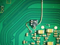
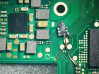
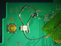
Then again, an oled will still need the shield to come off because of the clk point. Meh but for the rest it looks good.I spend 30-45 min from opening the shield to soldering two MOSFETs to the APU. This took me 5 minutes. It is a breakthrough!
Personally will wait for a few weeks for update on post install status of that mosfet type Mod and reliablity issues, if any.