Second time more precise
Good job.Second time more precise
I would like to try too, what do you use to scratch the pcb?
Second time more precise
Good job.Second time more precise
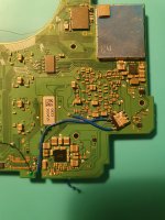
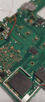
That's a chunky boy right thereUpdate from my previous post:
@Dee87 with the pin-point advice on what the problem was however I didn't know how to exactly do a dual irfhs8342 mosfet install on the one capacitor. But I realised it was insufficient power problem. Therefor I had resorted to fixing the chunky boy on the cap instead. Thanks @cgtchy0412 for the aon6554 mosfet advice and it worked like a charm. Didn't impede any fitting when putting things back and was a cleaner install (imo). Didn't have a pull down for this mosfet as its large enough to not have much or if any leakage of current. Glitches super fast and I will be using this way for my mosfet install in future. @abal1000x, good research on this side of the motherboard. It works great. have a look at the glitch times and the mosfet set up for the install:
edit - (so glad i didn't have to do another re-ball on it. phew)
Hope this ordeal helps someone down the line.
 . Cheers on getting it working.
Just a small observation, If I get *== on OLED and removed everything and got a black screen and the device is drawing 0.47 amps, does that rule out the poor wiring and rule in the dead APU?Sorry no other idea.
Time maybe 30 minPlease can share your opinion : about time cost, reliability, risk, difficulty when comparing with emmc reball?
Why would u use a grinder to get the past of the PCB ?Hi Guys. Go easy on your boy, but I messed up on this OLED big time. I kept getting *== and I would grind the CLK more and more to hopefully get a glitch going but instead, I ended up with this: (VIEWERS DISCRETION ADVISED):
Looking at the bright side, I've always wanted to learn how to work with emmc, I'll just give it a go and see if I could solder CLK directly into it.
Notes:
I still get 0.6v on multimeter when I point it on the trace right beneath the APU (tried soldering there, no luck)
I've changed the pico and re-wired the whole thing.
For new comers:
THIS IS INSTALLER's fault.
Update from my previous post:
@Dee87 with the pin-point advice on what the problem was however I didn't know how to exactly do a dual irfhs8342 mosfet install on the one capacitor. But I realised it was insufficient power problem. Therefor I had resorted to fixing the chunky boy on the cap instead. Thanks @cgtchy0412 for the aon6554 mosfet advice and it worked like a charm. Didn't impede any fitting when putting things back and was a cleaner install (imo). Didn't have a pull down for this mosfet as its large enough to not have much or if any leakage of current. Glitches super fast and I will be using this way for my mosfet install in future. @abal1000x, good research on this side of the motherboard. It works great. have a look at the glitch times and the mosfet set up for the install:
edit - (so glad i didn't have to do another re-ball on it. phew)
Hope this ordeal helps someone down the line.
.Hi , i want to reball and put wire on cmd pad, any suggestion about wiring route?Time maybe 30 min
Cost cheap stencil 10$ paste 10$ u can probbally reball at least 50 oleds with that
Risk if u keep the temp not to high I don't see any risk.
I even know someone who put the emmc on wring and there was no damage
Difficulty maybe a 6 out of 10
Post automatically merged:
Why would u use a grinder to get the past of the PCB ?
Just use a exacto knife or a needle.
U can still fix that with those green adapters u use to reball the emmc where there is cmd,clk,dat0 pin out.
U just need to make a connection to the rest of that clk line that is still ther e
Post automatically merged:
Well like I side it was the MOSFET and 2 would worked ;-).
Its pretty much the same way u install one just with 2
Just with some wires.
I suspect that would happened, some black screen, purple screen, etc.Just a small observation, If I get *== on OLED and removed everything and got a black screen and the device is drawing 0.47 amps, does that rule out the poor wiring and rule in the dead APU?
I've once had a v2 with that same error, but it boots to OFW, this OLED, does not.
I think no one yet do that.Hi , i want to reball and put wire on cmd pad, any suggestion about wiring route?
View attachment 383750
its a bit tricky but u could probally get it work with 0.1 enameled wir but if u really wanna go that way i would just get the adapter that @abal1000x sho in his post thats the easiest wayt to get clk&cmd out of the emmc pad.Hi , i want to reball and put wire on cmd pad, any suggestion about wiring route?
View attachment 383750
Not yet bro, not yet. I believe that you will manage to fix it with the green adapter, or in worst case scenario just swap the board with one of the previous ones where you damaged the apuThank you @Dee87 and @abal1000x for your valuable inputs, I do have a green adaptor that I bought and will use on this. This is going to be an exciting challenge. I no longer see any reason to get frustrated when killing a console, I learn and enjoy.
@rehius that's 10 now
Thank you @Dee87 and @abal1000x for your valuable inputs, I do have a green adaptor that I bought and will use on this. This is going to be an exciting challenge. I no longer see any reason to get frustrated when killing a console, I learn and enjoy.
@rehius that's 10 now
Thank you brother for the encouragement.Not yet bro, not yet. I believe that you will manage to fix it with the green adaptor, or in worst case scenario just swap the board with one of the previous ones where you damaged the apu
Stencil: https://www.aliexpress.com/item/1005004420982640.html
Do you have a diagram of the double Install? Or is it the same way as in the guide by ninjay? Too fiddly that way for me and takes too long.Time maybe 30 min
Cost cheap stencil 10$ paste 10$ u can probbally reball at least 50 oleds with that
Risk if u keep the temp not to high I don't see any risk.
I even know someone who put the emmc on wring and there was no damage
Difficulty maybe a 6 out of 10
Post automatically merged:
Why would u use a grinder to get the past of the PCB ?
Just use a exacto knife or a needle.
U can still fix that with those green adapters u use to reball the emmc where there is cmd,clk,dat0 pin out.
U just need to make a connection to the rest of that clk line that is still ther e
Post automatically merged:
Well like I side it was the MOSFET and 2 would worked ;-).
Its pretty much the same way u install one just with 2
Just with some wires.
When the glitch failed, have you tried changing the mosfet IRF8342 with another new IRF8342? Maybe its simply broken.Do you have a diagram of the double Install? Or is it the same way as in the guide by ninjay? Too fiddly that way for me and takes too long.
A polysh penGood job.
I would like to try too, what do you use to scratch the pcb?
Not sure if the guide is updated with the double backside MOSFET.Do you have a diagram of the double Install? Or is it the same way as in the guide by ninjay? Too fiddly that way for me and takes too long.
Oh do you mean connect them separately to the same cap or join the MOSFETS together at the S points like in the original guide by ninjay and then connect them to the cap? Like the normal soc way we used to do?Not sure if the guide is updated with the double backside MOSFET.
If not just need to solder the second one the same way in as the first one.
Well ich its to fiddly ur porb gonna need a different mosfet
Either of those two scenarios should work.Oh do you mean connect them separately to the same cap or join the MOSFETS together at the S points like in the original guide by ninjay and then connect them to the cap? Like the normal soc way we used to do?
Interesting, will give it a go on my next build. ThanksEither of those two scenarios should work.
I've modified about twenty OLEDs, all with adapters, and for the moment they're all working perfectly, and as far as I'm concerned, there's no comparison in terms of costs and processing times, the adapter is better. but chapeaux for those who do reballing but when you have to work 3 OLEDs in one evening...Please can share your opinion : about time cost, reliability, risk, difficulty when comparing with emmc reball?