


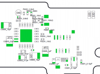
Found this schematic onlinenobody??
https://guide-images.cdn.ifixit.com/igi/SjfQg4dy3UfUnZ1n.full
Appears to be 1uF or 2.2uF 6.3v 0402 capacitor
Found this schematic onlinenobody??
Here you go.can anyone tell me, what component this is (the 3,3v point)? my ripped off.
Perfect, suspicions confirmed. I'll stick to the MX4 on the Switchs and save the new MX6 for the bigger stuff.The temp differences will be minimal for such a small TDP chip. Just ensure its at least mid range (deepcool MX3/4/5 etc), only ones worth replacing are the cpu die to shield and shield to heatpipe/heatsink. The pink junk to the rf shield isnt necessary to replace as the rf shield doesnt have enough mass to really help with cooling anyway.
The switch being such a small TDP cpu, the ROI of more expensive paste isnt there. The temp differences of more expensive pastes are only really noticeable on larger TDP packages.
Just ensure whatever paste you use isnt electrically conductive!
Example Arctic Silver. If you use a paste thats electrically conductive, any overflow on the cpu die will cause shorting on the caps etc.
Source: Myself, long term semi-competitive pc overclocker and console restorer/repairer.
Does this mean updating picofly in future we can use sdloader from toolbox?unlocked picofly does not rewrite the preloader (unless it's completely broken), people asked for that to be able to use sdloader from the hwfly, for example.
I just smoosh the pink junk back into a lump and reapply rf shield, but a correctly sized pad will also work fine for the picky customers who are opening the hardware that they paid you to work on? xDPerfect, suspicions confirmed. I'll stick to the MX4 on the Switchs and save the new MX6 for the bigger stuff.
I'll also now start replacing the pink stuff with cheap thermal pads JUST for a cleaner reassembly\future disassembly. Even though I'm w\ you on it being nigh pointless (clients get picky).
What about removing the copper tape (?) from the shielding altogether? Less layers equals better, correct?
Meh, for me, replacing the pink w\ pads is at least TRYING to stay near OG engineering. Lol, I actually JUST had my 1st client do that to me w\ an OGXB, "I always open my stuff to check it after".Does this mean updating picofly in future we can use sdloader from toolbox?
is this a planned implementation in a future release or currently existing in 2.5?
Thank you for your great work, I really enjoyed the install!
Post automatically merged:
I just smoosh the pink junk back into a lump and reapply rf shield, but a correctly sized pad will also work fine for the picky customers who are opening the hardware that they paid you to work on? xD
Honestly I would leave that in place, its a small die and the wifi/bt modules are fairly close to it so interference is highly likely, it also helps alleviate hot spots in the die by having a nice thermal spreader (same reason desktop cpu's have heat spreaders on top of their die's to compensate for poor application of thermal paste).
Just an FYI, you pulled up the BQ24193 schematic.Here you go.
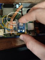
yes, I testedHas anyone tested the XIAO seeed rp2040 with 2.6? Digikey sells for around $5 which is slightly worse than Aliexpress but better than Amazons outrageous $15
Fkn whoops, I need another coffee obviously.Just an FYI, you pulled up the BQ24193 schematic.
The area of the board that the photo is referencing (I only know because it's my photo) is to the right of the memory, or the M92T36 chip area. Easy mistake to make, they have very similar layouts.
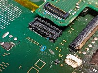
You need stencils, solder paste and scrapersThanks SQc04 I’ll see if somehow I can get a glob of solder onto that point. Man rst is so tiny.
I bought 36 awg FOR ALL POINTS. Anyone can confirm if it us okay? Just following sthethix videoI used AWG30 for GND and 3.3V and have no issues at all.

the fw2.6 installation is now available download itDoes anyone else have the same problem as me.I used PiCoFly FW2.5+unlock.uf2.View attachment 363265
nah RST isn't working for me. I keep getting light purple error and the other connections are goodYou need stencils, solder paste and scrapersView attachment 363260

I assume you have a v1 board, here is RST alternative solder point. It's on top of those 2 resistor, gold test points(both 2 same)nah RST isn't working for me. I keep getting light purple error and the other connections are good
bumpI bought 36 awg FOR ALL POINTS. Anyone can confirm if it us okay? Just following sthethix video
it's ok, up to 40 awgbump


 Saturday dude.


 JM
JM 