


Can send linkI’ve just received the “New” DAT0 adapter. They look like the “good” ones, am I right?
You are using an out of date browser. It may not display this or other websites correctly.
You should upgrade or use an alternative browser.
You should upgrade or use an alternative browser.
Staff Posts
Recent threadmarks
sharing files
Important Posts
Recent threadmarks
Firmwares
Yep, these look good. Just dont push too hard on them since the contact point looks a bit long and might bend sideways if alot of pressure is put to it.I’ve just received the “New” DAT0 adapter. They look like the “good” ones, am I right?

- Joined
- Sep 2, 2020
- Messages
- 1,342
- Trophies
- 0
- Age
- 39
- Location
- TORONTO
- Website
- form.jotform.com
- XP
- 2,277
- Country

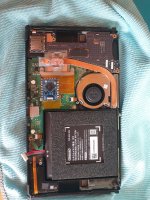
Very nice, thank you for your efforts and detail diagrams.@QuiTim @jkyoho thank you for your patience; here is the diagram for how I attached the status LED to the joy-con PCB. I removed the original home button LED in my installation, though it may be possible to mount the status LED directly next to the original, as the LED used on the RP2040 zero is smaller than the one on my seeed xiao RP2040. I also cut a hole in the rubber membrane between the button and the motherboard, to accommodate the LED and make certain the button could depress properly.
View attachment 380935
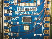
DIN point on the RP2040-Zero:
View attachment 380940
points to connect the LED DIN line from the RP2040 to the joy-con rail ribbon connector (first is v1/v2, second is oled):
View attachment 380939View attachment 380936
edit: while I have the photoshop file open, here is a diagram for how I wired my lite install as well. this one is far more practical and I have seen a couple other people do it since my first post, so it would be fun to see more home button lights moving forward
View attachment 380957
And just did test on my v2 with rp2040zero led. The led is small enough no need to cut the cushion.
For v2 board, JRST/pin6 can be solder on the resistor from picture blow.
Attachments
Last edited by jkyoho,

Can we use the official led? since the color doesn't matter, it's just long or short led pulse, no?@QuiTim @jkyoho thank you for your patience; here is the diagram for how I attached the status LED to the joy-con PCB. I removed the original home button LED in my installation, though it may be possible to mount the status LED directly next to the original, as the LED used on the RP2040 zero is smaller than the one on my seeed xiao RP2040. I also cut a hole in the rubber membrane between the button and the motherboard, to accommodate the LED and make certain the button could depress properly.
View attachment 380935
DIN point on the RP2040-Zero:
View attachment 380940
points to connect the LED DIN line from the RP2040 to the joy-con rail ribbon connector (first is v1/v2, second is oled):
View attachment 380939View attachment 380936
edit: while I have the photoshop file open, here is a diagram for how I wired my lite install as well. this one is far more practical and I have seen a couple other people do it since my first post, so it would be fun to see more home button lights moving forward
View attachment 380957
Last edited by HackMan37,
- Joined
- Sep 2, 2020
- Messages
- 1,342
- Trophies
- 0
- Age
- 39
- Location
- TORONTO
- Website
- form.jotform.com
- XP
- 2,277
- Country
No, unfortunately. I believe original LED from lite or right joycon is single white light LED.Can we use the official led? since the color doesn't matter, it's just long or short led, no?


What is your opinion if the error code is throws to the audio speaker.
Since speaker exist on every tipe of switch?
Long and short sounds using the Switch's existing speaker(s)? I LOVE the idea.
Then, no matter how long it takes to glitch, and if you can't see the LED, the user can hear a startup chime too.
Post automatically merged:
i'm doing all my installs with 100 ohm resistors for dat0/cmd and 47 ohm for clk. haven't had any ofw problems with any switch yet.
I recently got my 1st slow emmc and it's a SUPER bummer to basically finish the Switch and then go back and change\add resistors. Your posts about ONLY using 100\100\47 resistor sets are one of the few remaining reasons I continue to read the PFly threads.
I will now be doing all my installs the same way.
Last edited by LogicalMadness,
As the dat0 is only for OLED, do you use the 100 ohm resistor for the v1, v2 and lite as well?i'm doing all my installs with 100 ohm resistors for dat0/cmd and 47 ohm for clk. haven't had any ofw problems with any switch yet.
You need dat0 for all models. Oled just happens to be extra pain in the a§ to get toAs the dat0 is only for OLED, do you use the 100 ohm resistor for the v1, v2 and lite as well?
Apologies, yes, I didn't add the word adapter for the dat0.You need dat0 for all models. Oled just happens to be extra pain in the a§ to get to
So, my even with out a dat0 adapter its advised to use 100 ohm resistor?
Apologies, yes, I didn't add the word adapter for the dat0.
So, my even with out a dat0 adapter its advised to use 100 ohm resistor?
The adaptor it's just for soldering things, so yes, you need the resistor or design an adaptor that includes it.

Yes, resistors need to be added on all installations. And after a few months and alot of people doing this mod it seems that it is better to use 100ohm on dat0 and cmd and leave the same 47ohm on clk.Apologies, yes, I didn't add the word adapter for the dat0.
So, my even with out a dat0 adapter its advised to use 100 ohm resistor?
I used 47 on all 3 point in all my installations and I only needed to add second 47ohm (94ohm in total) to dat0 once in an upatched V1.
But I will use 100ohm in any future installs just to see what happens.
Last edited by QuiTim,

Look at this POS:
https://www.etsy.com/uk/listing/1500188493/mail-in-mod-service-for-oled-v1-v2-lite?click_key=816a8141040b903c5b9f744a8ee4bae922cf05d7:1500188493&click_sum=578b89d8&ref=shop_home_feat_3
"Kindly note that there are a few vendors on Etsy who offer a similar service at a lower cost. Their approach involves using a low-cost PR2040 board and tampering with the EMMC of your Switch. It is important to note that if Nintendo releases an update to combat copyright infringement, your Switch may become permanently unusable. On the other hand, the mod we use is safe and reversible. We can easily undo the mod if Nintendo introduces an update to prevent it."
WTF! This is the same seller that @lightninjay highlighted a week or so back about selling rp2040 with resistors and usb removed for £30. What a POS (From England).

47ohm (92ohm in total)
the math police is gonna write you a ticket for this

What a big piece of bullshit xDLook at this POS:
https://www.etsy.com/uk/listing/1500188493/mail-in-mod-service-for-oled-v1-v2-lite?click_key=816a8141040b903c5b9f744a8ee4bae922cf05d7:1500188493&click_sum=578b89d8&ref=shop_home_feat_3
"Kindly note that there are a few vendors on Etsy who offer a similar service at a lower cost. Their approach involves using a low-cost PR2040 board and tampering with the EMMC of your Switch. It is important to note that if Nintendo releases an update to combat copyright infringement, your Switch may become permanently unusable. On the other hand, the mod we use is safe and reversible. We can easily undo the mod if Nintendo introduces an update to prevent it."
WTF! This is the same seller that @lightninjay highlighted a week or so back about selling rp2040 with resistors and usb removed for £30. What a POS (From England).
LOL... I know the resistors need to be used on the install. I was asking, as you chimed in to my quoted question to another member, regarding using the 100 ohm on the dat0 and CLK. My question was specifically for the OLED because its a little different and requires the dat0 adapter. But, it seems like you answered my question -- I'll be using 100 ohm resistors for the dat0 and CLK and the 47 ohm other connections requiring a resistor on any version I mod.Yes, resistors need to be added on all installations. And after a few months and alot of people doing this mod it seems that it is better to use 100ohm on dat0 and cmd and leave the same 47ohm on clk.
I used 47 on all 3 point in all my installations and I only needed to add second 47ohm (92ohm in total) to dat0 once in an upatched V1.
But I will use 100ohm in any future installs just to see what happens.
Thanks for your help.
Hahahahhaha damn right they are, and a well deserved one. Better correct this one before everyone starts asking about my "secret" 92ohm setupthe math police is gonna write you a ticket for this
What a chuckleF*$&, they even used the graphic I made for all three switches in the guide, ripped it straight from the PDF, font and all.Look at this POS:
https://www.etsy.com/uk/listing/1500188493/mail-in-mod-service-for-oled-v1-v2-lite?click_key=816a8141040b903c5b9f744a8ee4bae922cf05d7:1500188493&click_sum=578b89d8&ref=shop_home_feat_3
"Kindly note that there are a few vendors on Etsy who offer a similar service at a lower cost. Their approach involves using a low-cost PR2040 board and tampering with the EMMC of your Switch. It is important to note that if Nintendo releases an update to combat copyright infringement, your Switch may become permanently unusable. On the other hand, the mod we use is safe and reversible. We can easily undo the mod if Nintendo introduces an update to prevent it."
WTF! This is the same seller that @lightninjay highlighted a week or so back about selling rp2040 with resistors and usb removed for £30. What a POS (From England).
What a P.O.S.
Wtf do they think ANY of these mods are doing? Every single one of these kinds of mods (HWFLY, Instinct, Picofly) rely on modifying a portion of the eMMC to be able to boot unsigned code.
I'll be using 100 ohm resistors for the dat0 and CLK and the 47 ohm other connections requiring a resistor on any version I mod.
not quite right, so to clarify:
dat0 - 100 ohm
cmd - 100 ohm
clk - 47 ohm
Attachments
Similar threads
- Replies
- 5
- Views
- 2K
- Replies
- 2
- Views
- 838
- Replies
- 42
- Views
- 7K
Site & Scene News
New Hot Discussed
-
-
39K views
New static recompiler tool N64Recomp aims to seamlessly modernize N64 games
As each year passes, retro games become harder and harder to play, as the physical media begins to fall apart and becomes more difficult and expensive to obtain. The... -
18K views
Majora’s Mask PC port 2Ship2Harkinian gets its first release
After several months of work, the Harbour Masters 64 team have released their first public build of 2Ship2Harkinian, a feature-rich Majora's Mask PC port. This comes... -
17K views
Anbernic reveals the RG35XXSP, a GBA SP-inspired retro handheld
Retro handheld manufacturer Anbernic has revealed its first clamshell device: the Anbernic RG35XXSP. As the suffix indicates, this handheld's design is inspired by... -
17K views
Mario Builder 64 is the N64's answer to Super Mario Maker
With the vast success of Super Mario Maker and its Switch sequel Super Mario Maker 2, Nintendo fans have long been calling for "Maker" titles for other iconic genres... -
13K views
The founder of Oculus is releasing a $199 FPGA Game Boy system
Palmer Luckey is known for his pursuits into the world of virtual reality, having founded Oculus and designed the Rift VR headset. Prior to the $2 billion dollar... -
13K views
Ubisoft reveals 'Assassin's Creed Shadows' which is set to launch later this year
Ubisoft has today officially revealed the next installment in the Assassin's Creed franchise: Assassin's Creed Shadows. This entry is set in late Sengoku-era Japan... -
13K views
RetroArch is now available in the Apple Store for iOS devices
Another day, another great emulator that makes its way into the Apple Store for more users to enjoy. With Apple opening its store up to videogame emulators earlier...by ShadowOne333 58 -
12K views
The Kingdom Hearts games are coming to Steam
After a little more than three years of exclusivity with the Epic Games Store, Square Enix has decided to bring their beloved Kingdom Hearts franchise to Steam. The... -
10K views
Nintendo takes down the Breath of the Wild randomizer mod from Gamebanana
Another day, another Nintendo DMCA takedown against fan-made content. Just a few minutes ago, Nintendo issued a DMCA takedown notice against a widely known and...by ShadowOne333 88 -
9K views
PS1 emulator "Gamma" has been added to the Apple Store for iOS devices
Continuing with the number of available retro emulators found in the Apple Store, after Apple's decision to finally allow videogame emulators on their store, another...by ShadowOne333 48
-
-
-
162 replies
The founder of Oculus is releasing a $199 FPGA Game Boy system
Palmer Luckey is known for his pursuits into the world of virtual reality, having founded Oculus and designed the Rift VR headset. Prior to the $2 billion dollar...by Chary -
145 replies
New static recompiler tool N64Recomp aims to seamlessly modernize N64 games
As each year passes, retro games become harder and harder to play, as the physical media begins to fall apart and becomes more difficult and expensive to obtain. The...by Chary -
104 replies
Majora’s Mask PC port 2Ship2Harkinian gets its first release
After several months of work, the Harbour Masters 64 team have released their first public build of 2Ship2Harkinian, a feature-rich Majora's Mask PC port. This comes...by Scarlet -
96 replies
Ubisoft reveals 'Assassin's Creed Shadows' which is set to launch later this year
Ubisoft has today officially revealed the next installment in the Assassin's Creed franchise: Assassin's Creed Shadows. This entry is set in late Sengoku-era Japan...by Prans -
90 replies
The Kingdom Hearts games are coming to Steam
After a little more than three years of exclusivity with the Epic Games Store, Square Enix has decided to bring their beloved Kingdom Hearts franchise to Steam. The...by Chary -
88 replies
Nintendo takes down the Breath of the Wild randomizer mod from Gamebanana
Another day, another Nintendo DMCA takedown against fan-made content. Just a few minutes ago, Nintendo issued a DMCA takedown notice against a widely known and...by ShadowOne333 -
67 replies
Select PlayStation 2 games are coming to PlayStation 5
Sony is once more attempting to reintroduce players to their older library of games by re-releasing classic PlayStation 2 titles onto the PlayStation Store. During...by Chary -
65 replies
Anbernic reveals the RG35XXSP, a GBA SP-inspired retro handheld
Retro handheld manufacturer Anbernic has revealed its first clamshell device: the Anbernic RG35XXSP. As the suffix indicates, this handheld's design is inspired by...by Prans -
65 replies
Mario Builder 64 is the N64's answer to Super Mario Maker
With the vast success of Super Mario Maker and its Switch sequel Super Mario Maker 2, Nintendo fans have long been calling for "Maker" titles for other iconic genres...by Scarlet -
63 replies
PlayStation State of Play May 2024 showcase - God of War: Ragnarok coming to PC
The latest State of Play is here. This is PlayStation's Summer showcase, providing updates to new updates on upcoming games and brand new reveals. The 35-minute...by Chary
-
Popular threads in this forum
General chit-chat
- No one is chatting at the moment.
-
-
-
-
-
-
-
-
 @
BigOnYa:
He was the ass of gbatemp, everyone knocked on him, I honestly felt bad, even though I was guilty myself, but he egged it all on himself,
@
BigOnYa:
He was the ass of gbatemp, everyone knocked on him, I honestly felt bad, even though I was guilty myself, but he egged it all on himself, -
-
-
@
BigOnYa:
I feel like gbatemp should make t-shirts or memorabilia to remember the lost ones. I bet the Polly shirts would sell out quick.
-
-
-
-
@
BigOnYa:
Your correct, Somebody would be guilty and there would be riots, then they storm the gbatemp capitol,
-
 @
K3Nv2:
Online or not there are still certain rights that judges would have no issue handing out a warrant over
@
K3Nv2:
Online or not there are still certain rights that judges would have no issue handing out a warrant over -
-
@
BigOnYa:
Honestly I'm scared to, from you, but ok, lemme turn on vpn, virtual machine, private browser first
-
-
-
@
BigOnYa:
That robot is here somewhere, I hear it moving around at night, but I haven't seen it for months.
-
@
BigOnYa:
Oh that laptop I give to ancientboi, so you been watching him for months, and he's been watching you
-
-
-