


Yes, they are rp2040 basedNo mate, the ones you sent are NOT rp2040 based and are NOT instinct-nx.
Post automatically merged:
View attachment 371702
Just arrived. All good. This is the INSTINCT-NX V6.
Last edited by josete2k,
Yes, they are rp2040 basedNo mate, the ones you sent are NOT rp2040 based and are NOT instinct-nx.
Post automatically merged:
View attachment 371702
Just arrived. All good. This is the INSTINCT-NX V6.
Oh yes you are right. sorry for that. I didn;t notice they were listed.Yes, they are rp2040 based
Curious how this chip is compared to the white board that some people have issues with the ground plane. Are u located in USA I tried to order this board and they told me they won't sell to USA which is a bummer, trying to locate the black instinct if it's better designed than the white oneNo mate, the ones you sent are NOT rp2040 based and are NOT instinct-nx.
Post automatically merged:
View attachment 371702
Just arrived. All good. This is the INSTINCT-NX V6.
with modchip disabled switch should work fine. probably something is damaged/shorted
Dam, thats concerning.
So leaving the CPU (SP1 and SP2) connected, wont cause cause the board not to boot?
I only soldered the 6 points on the board
CPU
CLK
CMD
3.3v
Dat0
RST
I'll check again and post some photos of the board
should be 18-20 ohms, 0. somthing ohm is straight up short to groundDam, thats concerning.
So leaving the CPU (SP1 and SP2) connected, wont cause cause the board not to boot?
I only soldered the 6 points on the board
CPU
CLK
CMD
3.3v
Dat0
RST
I'll check again and post some photos of the board
Post automatically merged:
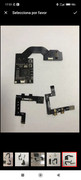
I did the measurements again:
diode mode on multimeter to ground
Black lead to ground and red to each points
A/CMD = 0.709 v
B/RST = OL
C/DAT0 = 0.520v
D/ CLK = 0.514 v
3.3V = 0.679 v
SP 1 = 0.001 v 00.5 ohms
SP 2 = 0.001 v 00.3 ohms
I compared the values to @ranma99vn on page 4
Looks like my SP1 and SP2 values are out by quite a bit
Pulled of the CPU cover and now saw there is a solder bridge between SP2 points covering the capacitor
Will try to correct this tonight
View attachment 371835
Thanks, I corrected the short, now its starting to OFW.should be 18-20 ohms, 0. somthing ohm is straight up short to ground
on the modchip, the 3 identical looking chips with 3 legs on the left side and 2 on the right. measure on the top right pin for each
do you get 1.2v, 1.8v and 3.3v respectively out of the 3 regulators (top-right pin for each)?
Thanks, I corrected the short, now its starting to OFW.
Back to installing the modship!
Post automatically merged:
Thanks @doom95, I corrected the solder bridge/short and re-installed the modchip.
Now the modship sometimes it boots into the no sd card screen, i think it did the initial training and now it also sometimes it boots to OFW and the red blinking lights (7-8 blinks at a time appears) - the red lights appear more often.
I measured the values when the everything is connected and running.
I get 3.3v, 1.7v, 1.1v
I can try to run putty, just looking for the download link to putty.
I'm UK based.Curious how this chip is compared to the white board that some people have issues with the ground plane. Are u located in USA I tried to order this board and they told me they won't sell to USA which is a bummer, trying to locate the black instinct if it's better designed than the white one

Try looking at AliExpress, they have loads of Switch modchips in store, plus they ship internationally.I'm UK based.
I know that, I quoted a guy US based that can't find them. I've already got mineTry looking at AliExpress, they have loads of Switch modchips in store, plus they ship internationally.
")
So the black board gets rid of the ground problems?Curious how this chip is compared to the white board that some people have issues with the ground plane. Are u located in USA I tried to order this board and they told me they won't sell to USA which is a bummer, trying to locate the black instinct if it's better designed than the white one
That's where I found the chip, only found 1 seller with the black instinct chip and he won't sell to America. I'd rather not do a picofly would like the instinct chip as it seems the best to install.Try looking at AliExpress, they have loads of Switch modchips in store, plus they ship internationally.
Not sure. That's what I was asking about, I know some people reported ground plane issues with the white board. At this point it's likely irrelevant as I can only find 1 shop on ali with the black board and he won't sell to AmericaSo the black board gets rid of the ground problems?
Brudi.....Thanks,
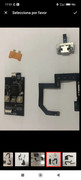
If you're going to use an expensive thermal paste I'd go a bit further and remove that nasty film they stuck on top of the CPU so to make direct contact to the heatsink. I think this film drastically worsen thermal conductivity.Finally installed!
Everything went super smoothly. All the cables provided had been used.
Super clean installation, only takes 2 flying wires. I used AWG34 enameled wire, they were DAT0 and RESET.
Bare in mind that the RST pin in the OLED version gives an open circuit. I lost 2h trying to understand it haha.
The capacitors on the cpu package will read about 18/20ohm each. If you read about 10ohm, it means two are shorted together.
Now Doing an EMMC backup and so far so good.
Injection times are ridiculously fast.
I hope to see +99fps with the Kryonaut lol.
View attachment 372070View attachment 372071View attachment 372072
Hi all, would need your help on the red blinking light below. I am worried that I spoilt the switch D:
Rp2040 version available to purchase:
https://a.aliexpress.com/_EGV7HQD
The seller told me that so far the firmware used cannot be upgraded but to work ATM it doesn't need to.
I think he simply ment that there are no updates.
Moreover he strongly advise AGAINST the lite version. "It's bugged".
Hi, here are my diode readings.If you're going to use an expensive thermal paste I'd go a bit further and remove that nasty film they stuck on top of the CPU so to make direct contact to the heatsink. I think this film drastically worsen thermal conductivity.
Post automatically merged:
Check your diode readings. Also check reverse polarity on your dat0.
This is exactly the same thjing thats happening to me, im getting no reading from the reset point to ground, but im using diode mode,If you're going to use an expensive thermal paste I'd go a bit further and remove that nasty film they stuck on top of the CPU so to make direct contact to the heatsink. I think this film drastically worsen thermal conductivity.
Post automatically merged:
Check your diode readings. Also check reverse polarity on your dat0.
same readings effectively, I have made a post with detailed photos and a video similar to yours, im not going to post here but if you want to reference to see if there is anything different to mine, i guess it will all te the same to get the same error lightHi, here are my diode readings.
3.3V = 0.830v
D/CLK = 0.645v
A/CMD = 0.694v
C/DAT0 = 0.720v
B/RST = 0v


