Hacking INSTINCT-NX Chip

  • Thread starter HWE
  • Start date
  • Views 139,333
  • Replies 447
  • Likes 1

Ferz1984

Member
Newcomer
Joined
Jun 20, 2023
Messages
22
Trophies
0
Age
39
XP
129
Country
Greece
I hope someone can help me...

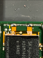
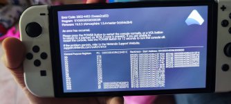
I modded my Oled Switch (3 months ago) with INSTINCT NX V6 and it was working fine... as I was playing it froze and gave me an atmosphere error screen... I turned it off and after that, I had a black screen….

After some attempts, it finally booted to Heakte and I restored the EMMC successfully, tested and seemed okay without errors...

I installed some games and as I was playing Mario Kart and again after 2 hours atmosphere error screen.

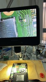
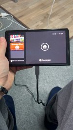
Since then the switch has been on a black screen and the chip is blinking white…
(When connected to computer it recognises as Nintendo Switch APX Device...)

I am sure that the emmc again is corrupted.

Is there any way to restore it with INSTINCT NX? (I have read that with HWFly modchip you can use Hwfly nx firmware which allows for glitching into an empty Nand so you can load heakte and restore the backup...)

What else can I do to restore it? Only remove it and restore it with programmer? (which I don't have )

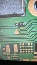
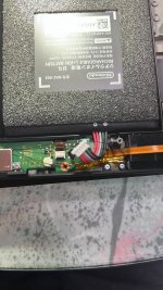
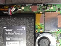
I am sure that the chip is installed correctly... at first, it was installed with wires, I had tested all the points, and were okay...
Just for testing, I removed it and tried to boot the switch without the modchip, and again black screen..

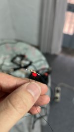
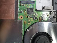
Now I have installed it with the flex cable and not enameled wires...(I don't like it... think I will remove it and use the enameled wires again)...

I have tested all the points with a multimeter and everything seems ok...

What else should I have to check? I am stuck now...

Later i will try with putty to see the chip status..

Any suggestions are welcome
 

Attachments

  • 393985-68ac7bf19b9992e18d6e621f553434af.mp4
    6.5 MB
  • IMG_20230914_161647.jpg
    IMG_20230914_161647.jpg
    2.5 MB · Views: 65
Last edited by Ferz1984,

Blakejansen

Well-Known Member
Member
Joined
Aug 17, 2021
Messages
614
Trophies
0
Age
40
XP
1,508
Country
United States
I am getting really inconsistent boot times. Sometimes the oled instaboots, but other times I have to wait up to 2 minutes to get it to boot into the no-sd screen. I know that the connections are soldered because I can get a glitch sometimes instantly.

I really need help and no one seems to have a similar problem to mine.
 

Jamisons

New Member
Newbie
Joined
Oct 18, 2023
Messages
2
Trophies
0
Age
32
XP
8
Country
New Zealand
I am getting really inconsistent boot times. Sometimes the oled instaboots, but other times I have to wait up to 2 minutes to get it to boot into the no-sd screen. I know that the connections are soldered because I can get a glitch sometimes instantly.

I really need help and no one seems to have a similar problem to mine.
What is your modchips LED light doing while its taking a long time to glitch?
 

tejadon

Member
Newcomer
Joined
Nov 11, 2023
Messages
5
Trophies
0
Age
33
XP
21
Country
Spain
Hello:I installed instinct nx v6 two days ago and it does the training correctly but the console does not turn on, leaving the screen black. I reviewed the welds on all sides with a microscope and I did not see any short circuits. Right now I'm going over them again and I'm cleaning up traces of flux although I don't think that's what it's about because it's not conductive. I am measuring and the values are correct. On the other hand, I am measuring the nearby components to see if any are burned or provide continuity and everything seems to be correct. The only thing that has caught my attention are the components near the USB charging port that I did notice by measuring their ends although I have not given it importance because they give 10ohms...I do not know what else to do. some help?
 

Attachments

  • IMG_4322.mov
    21.6 MB

Stidwack

Active Member
Newcomer
Joined
Aug 30, 2023
Messages
25
Trophies
0
Age
32
XP
247
Country
United States
Hello:I installed instinct nx v6 two days ago and it does the training correctly but the console does not turn on, leaving the screen black. I reviewed the welds on all sides with a microscope and I did not see any short circuits. Right now I'm going over them again and I'm cleaning up traces of flux although I don't think that's what it's about because it's not conductive. I am measuring and the values are correct. On the other hand, I am measuring the nearby components to see if any are burned or provide continuity and everything seems to be correct. The only thing that has caught my attention are the components near the USB charging port that I did notice by measuring their ends although I have not given it importance because they give 10ohms...I do not know what else to do. some help?

If you hold vol+ and vol- together while trying to boot, does it boot to stock firmware?

I had an Instinct chip that functioned "fine" as you showed in your video, but there were shorts on the chip itself that, for whatever reason, would not allow the Switch to boot even after going through the training and finally showing the green success LED. I swapped it out for another Instinct and it booted up perfectly.

If you're sure that all your solder points are reading as they should, it could even be a problem with the OLED display. Try reseating the ribbon cable for the screen?
 

tejadon

Member
Newcomer
Joined
Nov 11, 2023
Messages
5
Trophies
0
Age
33
XP
21
Country
Spain
If you hold vol+ and vol- together while trying to boot, does it boot to stock firmware?

I had an Instinct chip that functioned "fine" as you showed in your video, but there were shorts on the chip itself that, for whatever reason, would not allow the Switch to boot even after going through the training and finally showing the green success LED. I swapped it out for another Instinct and it booted up perfectly.

If you're sure that all your solder points are reading as they should, it could even be a problem with the OLED display. Try reseating the ribbon cable for the screen?
Currently I have it disassembled again because I was checking the solders and I realized through the microscope that there was a solder bridge between one of the tin points on the right side and the ground. Here I attach a photo for guidance (yellow line). The multimeter gave continuity so this may have something to do with it. what do you think?
 

Attachments

  • dat0.png
    dat0.png
    383.3 KB · Views: 50

Stidwack

Active Member
Newcomer
Joined
Aug 30, 2023
Messages
25
Trophies
0
Age
32
XP
247
Country
United States
Currently I have it disassembled again because I was checking the solders and I realized through the microscope that there was a solder bridge between one of the tin points on the right side and the ground. Here I attach a photo for guidance (yellow line). The multimeter gave continuity so this may have something to do with it. what do you think?

good catch. yeah I would clean that up if you haven't already and give it another test after checking all your other points
 

eddz

Well-Known Member
Newcomer
Joined
Dec 4, 2023
Messages
53
Trophies
0
XP
117
Country
Australia
Thanks to all for all the tips I've found in this thread. I'm planning on doing the install for the Instinct-NX v6 (black board) in an OLED NS. I'll be using both flex cables. Will report back once complete.
 

Badablek

Well-Known Member
Member
Joined
Jan 23, 2006
Messages
517
Trophies
1
Age
43
XP
2,924
Country
France
Currently I have it disassembled again because I was checking the solders and I realized through the microscope that there was a solder bridge between one of the tin points on the right side and the ground. Here I attach a photo for guidance (yellow line). The multimeter gave continuity so this may have something to do with it. what do you think?
Sorry for the dumb question, but...it seems there is no trace of welding on your photo...Did you ever solder the Dat0 point to your Instinct-NX chip (point C) ? :mellow:

Yes, I know, my question seems really dumb, but Dat0 should be grey (tin) on your photo, not yellow (copper) :moogle:
 

eddz

Well-Known Member
Newcomer
Joined
Dec 4, 2023
Messages
53
Trophies
0
XP
117
Country
Australia
1701775779336.png


Install isn't going very smoothly. I managed to knock off a couple of the caps below the CPU, but put them back in place and tested and booting to OFW before I installed the 2 flex cables for the Instinct-NX v6 (new black board).

But once I soldered in place the two flex cables (one of them goes below the CPU and connects to the caps, the other one connects to 3.3v, CLK, DAT0, and CMD) and tried to test boot to OFW again, but now the screen won't turn on. Is it supposed to boot to OFW if only the flex cables are installed? I would assume so.

Anyway, I installed the chip and got the above serial output. I checked CLK (D) point and I'm getting 0.608v before switching it on. But while it's on point D is showing OL. Is this expected?

Any help will be appreciated. Many thanks.
Post automatically merged:


1701776712080.png


This is the Instinc-NX v6 (black) installed. I don't have any pics of the soldered points until I pull it apart again.
 
Last edited by eddz,

tejadon

Member
Newcomer
Joined
Nov 11, 2023
Messages
5
Trophies
0
Age
33
XP
21
Country
Spain
Sorry for the dumb question, but...it seems there is no trace of welding on your photo...Did you ever solder the Dat0 point to your Instinct-NX chip (point C) ? :mellow:

Yes, I know, my question seems really dumb, but Dat0 should be grey (tin) on your photo, not yellow (copper) :moogle:
Hello, I had a series of funny problems... I removed the chip and the console turned on with a purple screen, so when I checked myself I realized that I burned the resistor where the cmd cable is soldered. I had to fix it with a normal resistor and the console is working again, but without a chip. For now I'll leave it like this, I managed with what I had... I'm attaching photos.
Post automatically merged:

View attachment 407439

Install isn't going very smoothly. I managed to knock off a couple of the caps below the CPU, but put them back in place and tested and booting to OFW before I installed the 2 flex cables for the Instinct-NX v6 (new black board).

But once I soldered in place the two flex cables (one of them goes below the CPU and connects to the caps, the other one connects to 3.3v, CLK, DAT0, and CMD) and tried to test boot to OFW again, but now the screen won't turn on. Is it supposed to boot to OFW if only the flex cables are installed? I would assume so.

Anyway, I installed the chip and got the above serial output. I checked CLK (D) point and I'm getting 0.608v before switching it on. But while it's on point D is showing OL. Is this expected?

Any help will be appreciated. Many thanks.
Post automatically merged:


View attachment 407442

This is the Instinc-NX v6 (black) installed. I don't have any pics of the soldered points until I pull it apart again.
If you disconnect the two flex cables that go to the chip, does the console start or not?Do the point values give you between 450 and 800?Does point D say OL? Check in continuity mode that there is no ground connection. Place the black tip anywhere on the chassis and the red tip on point D and check for beeps.
 

Attachments

  • CA0A0D88-661F-4DC5-8A72-25241ACAE75B.jpeg
    CA0A0D88-661F-4DC5-8A72-25241ACAE75B.jpeg
    1.1 MB · Views: 49
  • 20BAEA29-C0EE-41B4-938B-2A0D0165C4ED.jpeg
    20BAEA29-C0EE-41B4-938B-2A0D0165C4ED.jpeg
    2.1 MB · Views: 40
  • A541E34C-4262-451D-AB1A-867BFA904466.jpeg
    A541E34C-4262-451D-AB1A-867BFA904466.jpeg
    675.1 KB · Views: 39
  • BB1E13E3-A7D4-4CDE-82B9-FA85D3E9A71C.jpeg
    BB1E13E3-A7D4-4CDE-82B9-FA85D3E9A71C.jpeg
    1.4 MB · Views: 38
  • IMG_4419.jpeg
    IMG_4419.jpeg
    2 MB · Views: 41
  • IMG_4418.jpeg
    IMG_4418.jpeg
    1.7 MB · Views: 41
  • 9C41FB5B-484E-48BF-A955-DC1E2433ABC3.jpeg
    9C41FB5B-484E-48BF-A955-DC1E2433ABC3.jpeg
    869.1 KB · Views: 44
  • Like
Reactions: Badablek

eddz

Well-Known Member
Newcomer
Joined
Dec 4, 2023
Messages
53
Trophies
0
XP
117
Country
Australia
If you disconnect the two flex cables that go to the chip, does the console start or not?Do the point values give you between 450 and 800?Does point D say OL? Check in continuity mode that there is no ground connection. Place the black tip anywhere on the chassis and the red tip on point D and check for beeps.

No, it doesnt start. I'm assuming it should start even with the 2 flex cables soldered in place (and the instinct nx removed). Today I will try de-soldering the flex cables one-by-one and see if it starts.
 

tejadon

Member
Newcomer
Joined
Nov 11, 2023
Messages
5
Trophies
0
Age
33
XP
21
Country
Spain
No, it doesnt start. I'm assuming it should start even with the 2 flex cables soldered in place (and the instinct nx removed). Today I will try de-soldering the flex cables one-by-one and see if it starts.
According to the output of the series, the problem is that it is not getting value from the clk. Check that it is well welded because that point is very delicate and tends to come loose. Also measure whether you get value.
 

eddz

Well-Known Member
Newcomer
Joined
Dec 4, 2023
Messages
53
Trophies
0
XP
117
Country
Australia
IT'S ALIVE!!!


So I had two main issues. I wasn't putting the OLED ribbon cable in all the way which explains why the screen wasn't turning on. TIP: Be very gentle with this cable. When you put the cable in and put the locking flap down you shouldn't be able to see any copper of the pins on the ribbon.

The other issue was the point D (CLK) was soldered just fine, but the track on the board (that goes under the nvidia SoC) was broken. I bridged it using enameled wire and I was able to glitch and boot.

Other things I did was resolder all points for the chip and reflow the eMMC. I'm not sure if this was needed as all those points were reading fine, but I did it anyway and retested.

All photos below are after the 'fix' and of a working Instinct-NX install.
1701828624788.png

Point A is reading 0.598V
Point C is reading 0.678V

1701828770003.png

3.3V is reading 0.708V

1701828811883.png
Here you can see the D (CLK) trace is broken. I have no idea how it happened, I was being so damn careful.

1701828879588.png

I bridged the break using a thing piece of wire. It worked. Phew!
Point D is reading 0.701V (interestingly, it was reading about the same before bridging that cut track)

1701828973085.png

I reflowed the eMMC according to the instructions provided here (https://gbatemp.net/threads/oled-v6-chip-black-screen.643295/#post-10304661).
C (DAT0) is reading 0.678V

[Not pictured] SP1 15.6 Ohms, SP2 14.1 Ohms

1701829049056.png

Success! Thanks to all who've helped and were kind enough to post their knowledge/experiences here.


WARNING to anyone considering doing this mod.
I have ~30 years of hobbyist-level soldering experience and I really wasn't prepared for how difficult this install was. I bought a soldering microscope and used the tools I already had available. I quickly realised that my tools are far inferior to what are needed to do this job properly. The flux I used was messy and the soldering iron wasn't made for such fine jobs.
PLEASE reconsider attempting this hack if you haven't played around with micro soldering before.
If you're still going to do it anyway, then consider buying good flux, soldering iron with T12 tip, reflow/heat gun, good solder, good tweezers, lots of patience, and a steady hand.
 
Last edited by eddz,
  • Like
Reactions: DebianLoriX

Hassal

Well-Known Member
Member
Joined
Apr 22, 2023
Messages
567
Trophies
0
Age
24
XP
514
Country
United Arab Emirates
IT'S ALIVE!!!


So I had two main issues. I wasn't putting the OLED ribbon cable in all the way which explains why the screen wasn't turning on. TIP: Be very gentle with this cable. When you put the cable in and put the locking flap down you shouldn't be able to see any copper of the pins on the ribbon.

The other issue was the point D (CLK) was soldered just fine, but the track on the board (that goes under the nvidia SoC) was broken. I bridged it using enameled wire and I was able to glitch and boot.

Other things I did was resolder all points for the chip and reflow the eMMC. I'm not sure if this was needed as all those points were reading fine, but I did it anyway and retested.

All photos below are after the 'fix' and of a working Instinct-NX install.
View attachment 407520
Point A is reading 0.598V
Point C is reading 0.678V

View attachment 407521
3.3V is reading 0.708V

View attachment 407522Here you can see the D (CLK) track is broken. I have no idea how it happened, I was being so damn careful.

View attachment 407523
I bridged the break using a thing piece of wire. It worked. Phew!
Point D is reading 0.701V (interestingly, it was reading about the same before bridging that cut track)

View attachment 407524
I reflowed the eMMC according to the instructions provided here (https://gbatemp.net/threads/oled-v6-chip-black-screen.643295/#post-10304661).
C (DAT0) is reading 0.678V

[Not pictured] SP1 15.6 Ohms, SP2 14.1 Ohms

View attachment 407525
Success! Thanks to all who've helped and were kind enough to post their knowledge/experiences here.


WARNING to anyone considering doing this mod.
I have ~30 years of hobbyist-level soldering experience and I really wasn't prepared for how difficult this install was. I bought a soldering microscope and used the tools I already had available. I quickly realised that my tools are far inferior to what are needed to do this job properly. The flux I used was messy and the soldering iron wasn't made for such fine jobs.
PLEASE reconsider attempting this hack if you haven't played around with micro soldering before.
If you're still going to do it anyway, then consider buying good flux, soldering iron with T12 tip, reflow/heat gun, good solder, good tweezers, lots of patience, and a steady hand.
Reflowing was unnecessary in your case. General assumption for breaking CLK is digging too deep into the blind via resulting in cutting the connection.
 

Site & Scene News

Popular threads in this forum

General chit-chat
Help Users
    K3Nv2 @ K3Nv2: https://youtube.com/shorts/BiY0vNuu1eg?si=0nwmSHWeLkfcJJ__