

You are using an out of date browser. It may not display this or other websites correctly.
You should upgrade or use an alternative browser.
You should upgrade or use an alternative browser.

- Joined
- Sep 2, 2020
- Messages
- 1,282
- Trophies
- 0
- Age
- 39
- Location
- TORONTO
- Website
- form.jotform.com
- XP
- 2,212
- Country

If McFly is only using the middle 2pin as CPU Line for mosfet GATE line, fixing this issue should be fairly simple replacing the FPC connector with a top&bottom contacts NEW connector,instead of bottom only.
- CPU flex connector works with V3 CPU ribbion facing downwards but ones like lite ribbion and various other ones that facing upwards won't work

The Hirose FH34 connector I chose was supposed to be double sided but didn't seem to work, I'll see if I can find another low profile oneIf McFly is only using the middle 2pin as CPU Line for mosfet GATE line, fixing this issue should be fairly simple replacing the FPC connector with a top&bottom contacts NEW connector,instead of bottom only.

Great job! Love to see McFly PicoFlying!!I'm greatful to Saliciae for giving the chance to test one of his new McFly board. Pleasee pictures below of my install, the board works flawlessly and compared in difficulty level I'd put it on the same level as installing an OLED HWFLY V3/V4 via wire install. I've just literaly finished this like 10 minutes ago, but as I spend time on it I'm sure I'll have more feedback to give. The three main things I could up with straight are:
- Rotate the solder pads 90 degrees towards the fan, makes wires routing easier and neater for almost any switch install
- Label the pads from top of the board, I took a picture of the board from beneath and used a reference once its mounted but someone can easily solder the wrong wire to the wrong pad
- CPU flex connector works with V3 CPU ribbion facing downwards but ones like lite ribbion and various other ones that facing upwards won't work
View attachment 365589
View attachment 365594
View attachment 365595
View attachment 365596
View attachment 365597
View attachment 365590
View attachment 365591
View attachment 365592
View attachment 365593
Question: I remember that @Saliciae made a quite slim board, though did you had to cut the shield of the Lite? With RP2040-zero (no USB no buttons) positioned on the same place the shield needs cutting or there will be a lot of pressure after closing.

I've not put the metal sheet back on yet but i'll update, however from eye inspction it looks like it may not need to be cut.Great job! Love to see McFly PicoFlying!!
Question: I remember that @Saliciae made a quite slim board, though did you had to cut the shield of the Lite? With RP2040-zero (no USB no buttons) positioned on the same place the shield needs cutting or there will be a lot of pressure after closing.
Quick browse on LCSC shows all 6 pin 0.5mm pitch double sided connctors wwith a slim height are either the hirose or a knockoff of the hirose, i'm going to fiddle with the board i have to hand and see if i can find out why it wasn't working in both orientations
Pin labels on the top side would make the board about 10-15% wider for no reason, I could put the labels on another snap off section aligned with the pads so it can be snapped off before soldering and used as a guide, it would line up with the pads and register against the connector so it's obvious which way round it went, interested to hear people's opinions on this approach. I'd really like to keep it as small as humanly possible
Post automatically merged:
Pin labels on the top side would make the board about 10-15% wider for no reason, I could put the labels on another snap off section aligned with the pads so it can be snapped off before soldering and used as a guide, it would line up with the pads and register against the connector so it's obvious which way round it went, interested to hear people's opinions on this approach. I'd really like to keep it as small as humanly possible
Last edited by Saliciae,
If adding label on top would increase size then scrap that, would using one letter instead makes differece like on the HWFLY A, C, D, V (for 3.3v) and G for (GND)?Quick browse on LCSC shows all 6 pin 0.5mm pitch double sided connctors wwith a slim height are either the hirose or a knockoff of the hirose, i'm going to fiddle with the board i have to hand and see if i can find out why it wasn't working in both orientations
Post automatically merged:
Pin labels on the top side would make the board about 10-15% wider for no reason, I could put the labels on another snap off section aligned with the pads so it can be snapped off before soldering and used as a guide, it would line up with the pads and register against the connector so it's obvious which way round it went, interested to hear people's opinions on this approach. I'd really like to keep it as small as humanly possible

silkscreening the point names wont take up spaceIf adding label on top would increase size then scrap that, would using one letter instead makes differece like on the HWFLY A, C, D, V (for 3.3v) and G for (GND)?
Everything is so compressed on this board, especially on the new version that it really will take up space. if you look at the new picture (https://gbatemp.net/threads/mcfly-an-rp2040-board-compatible-with-picofly.629024/post-10128107) and take into account text size requirements and silk clearance requirements i'll have to shuffle components around to make it all work even with just one character labels.silkscreening the point names wont take up space
https://hackaday.com/tag/text-in-pad/Everything is so compressed on this board, especially on the new version that it really will take up space. if you look at the new picture (https://gbatemp.net/threads/mcfly-an-rp2040-board-compatible-with-picofly.629024/post-10128107) and take into account text size requirements and silk clearance requirements i'll have to shuffle components around to make it all work even with just one character labels.
?

holy shit I was just about to post this. One of the few domains I have visted every week over the last decade.

Nice trick. So obvious yet i have never thought about it. Thanks for sharing it.

omg it's so tiny and PURPLE!I'm greatful to Saliciae for giving the chance to test one of his new McFly board. Pleasee pictures below of my install, the board works flawlessly and compared in difficulty level I'd put it on the same level as installing an OLED HWFLY V3/V4 via wire install. I've just literaly finished this like 10 minutes ago, but as I spend time on it I'm sure I'll have more feedback to give. The three main things I could up with straight are:
- Rotate the solder pads 90 degrees towards the fan, makes wires routing easier and neater for almost any switch install
- Label the pads from top of the board, I took a picture of the board from beneath and used a reference once its mounted but someone can easily solder the wrong wire to the wrong pad
- CPU flex connector works with V3 CPU ribbion facing downwards but ones like lite ribbion and various other ones that facing upwards won't work
View attachment 365589
View attachment 365594
View attachment 365595
View attachment 365596
View attachment 365597
View attachment 365590
View attachment 365591
View attachment 365592
View attachment 365593

New version is even smaller, waiting on more feedback from the rest of the testers then it'll get any changes needed and releasedomg it's so tiny and PURPLE!

Is there any chance of ever adding a place for an optional onboard Mosfet? I mean the chip sits very close to the APU anyway and it's worth giving it a tryNew version is even smaller, waiting on more feedback from the rest of the testers then it'll get any changes needed and released
Last edited by KarimPolska,

Today i received @Saliciae Mcfly prototype and test fitted in to a v2 with Samsung mmc , one mosfet to cpu (cables can be a lot of shorter , i just wanted to test if it work correct)
The metal shield fits nice with a little bump without any cutting , and the back cover closes without any problem
next days i will test it in an oled
i would like the solder pads be next to the flex cable connector from the right side in order to be more easy install and with short cables when a flex ribbon is used and of course like the other member said i would like the labeling from the top side...
Beside that i believe is a very nice and little board
Thanks for trying it! Labelling from the top side will increase the size of the board which i'm really not keen on, hopefully once the board is released the documentation can be a good substitute. What do you mean by solder pads next to the flex cable connector on the right side? do you want the solder pads and flex to swap positions?
I have a question, how should one position the chip to use the latest (v5 as of now) HWFly ribbon cabble in a switch lite? Or should I go with a different flex cable?
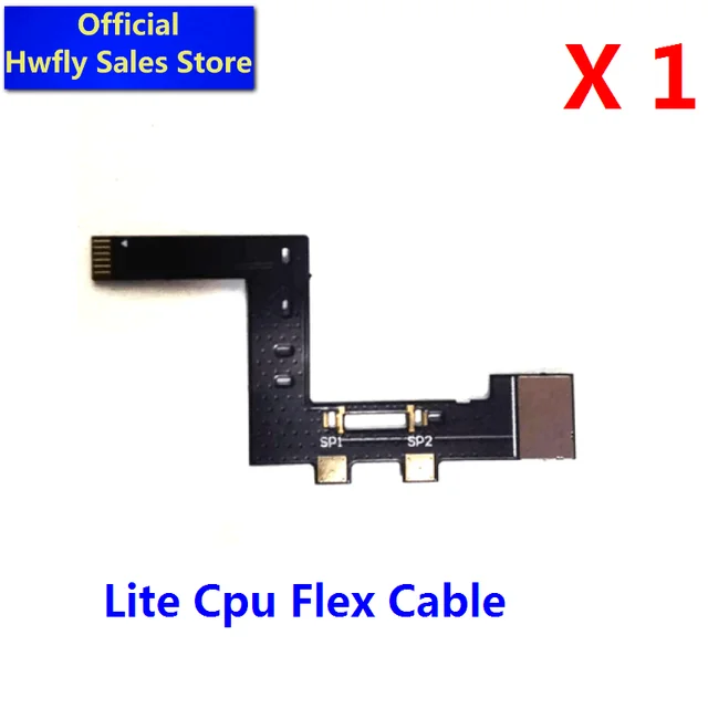
Found the cables here.
Oh and I almost forgot, should I get this as well ? Straight Cable For Lite
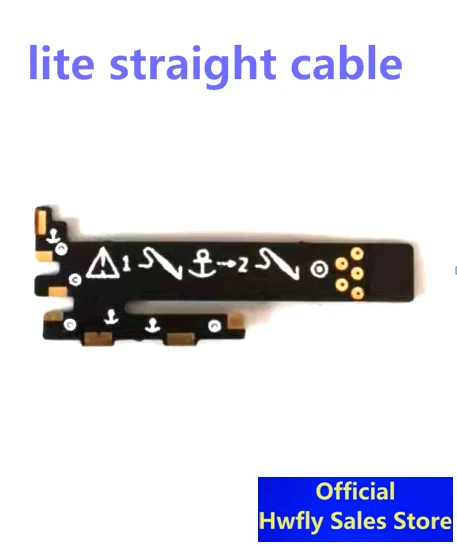
Found the cables here.
Oh and I almost forgot, should I get this as well ? Straight Cable For Lite
Last edited by Kinokoda,
I think the HWFLY lite and oled flex cables have the same spacing etc since its the same chip and yep thats the cableI have a question, how should one position the chip to use the latest (v5 as of now) HWFly ribbon cabble in a switch lite? Or should I go with a different flex cable?
Found the cables here.
Oh and I almost forgot, should I get this as well ? Straight Cable For Lite
Similar threads
- Replies
- 3K
- Views
- 521K
- Replies
- 14
- Views
- 6K
- Replies
- 3
- Views
- 4K
- Replies
- 21
- Views
- 12K
- Replies
- 0
- Views
- 2K
Site & Scene News
New Hot Discussed
-
-
23K views
Wii U and 3DS online services shutting down today, but Pretendo is here to save the day
Today, April 8th, 2024, at 4PM PT, marks the day in which Nintendo permanently ends support for both the 3DS and the Wii U online services, which include co-op play...by ShadowOne333 179 -
18K views
Nintendo Switch firmware update 18.0.1 has been released
A new Nintendo Switch firmware update is here. System software version 18.0.1 has been released. This update offers the typical stability features as all other... -
16K views
The first retro emulator hits Apple's App Store, but you should probably avoid it
With Apple having recently updated their guidelines for the App Store, iOS users have been left to speculate on specific wording and whether retro emulators as we... -
16K views
Delta emulator now available on the App Store for iOS
The time has finally come, and after many, many years (if not decades) of Apple users having to side load emulator apps into their iOS devices through unofficial...by ShadowOne333 96 -
15K views
MisterFPGA has been updated to include an official release for its Nintendo 64 core
The highly popular and accurate FPGA hardware, MisterFGPA, has received today a brand new update with a long-awaited feature, or rather, a new core for hardcore...by ShadowOne333 54 -
12K views
TheFloW releases new PPPwn kernel exploit for PS4, works on firmware 11.00
TheFlow has done it again--a new kernel exploit has been released for PlayStation 4 consoles. This latest exploit is called PPPwn, and works on PlayStation 4 systems... -
11K views
Nintendo takes down Gmod content from Steam's Workshop
Nintendo might just as well be a law firm more than a videogame company at this point in time, since they have yet again issued their now almost trademarked usual...by ShadowOne333 113 -
10K views
A prototype of the original "The Legend of Zelda" for NES has been found and preserved
Another video game prototype has been found and preserved, and this time, it's none other than the game that spawned an entire franchise beloved by many, the very...by ShadowOne333 31 -
9K views
Anbernic reveals specs details of pocket-sized RG28XX retro handheld
Anbernic is back with yet another retro handheld device. The upcoming RG28XX is another console sporting the quad-core H700 chip of the company's recent RG35XX 2024... -
9K views
Nintendo "Indie World" stream announced for April 17th, 2024
Nintendo has recently announced through their social media accounts that a new Indie World stream will be airing tomorrow, scheduled for April 17th, 2024 at 7 a.m. PT...by ShadowOne333 53
-
-
-
179 replies
Wii U and 3DS online services shutting down today, but Pretendo is here to save the day
Today, April 8th, 2024, at 4PM PT, marks the day in which Nintendo permanently ends support for both the 3DS and the Wii U online services, which include co-op play...by ShadowOne333 -
113 replies
Nintendo takes down Gmod content from Steam's Workshop
Nintendo might just as well be a law firm more than a videogame company at this point in time, since they have yet again issued their now almost trademarked usual...by ShadowOne333 -
97 replies
The first retro emulator hits Apple's App Store, but you should probably avoid it
With Apple having recently updated their guidelines for the App Store, iOS users have been left to speculate on specific wording and whether retro emulators as we...by Scarlet -
96 replies
Delta emulator now available on the App Store for iOS
The time has finally come, and after many, many years (if not decades) of Apple users having to side load emulator apps into their iOS devices through unofficial...by ShadowOne333 -
79 replies
Nintendo Switch firmware update 18.0.1 has been released
A new Nintendo Switch firmware update is here. System software version 18.0.1 has been released. This update offers the typical stability features as all other...by Chary -
76 replies
TheFloW releases new PPPwn kernel exploit for PS4, works on firmware 11.00
TheFlow has done it again--a new kernel exploit has been released for PlayStation 4 consoles. This latest exploit is called PPPwn, and works on PlayStation 4 systems...by Chary -
55 replies
Nintendo Switch Online adds two more Nintendo 64 titles to its classic library
Two classic titles join the Nintendo Switch Online Expansion Pack game lineup. Available starting April 24th will be the motorcycle racing game Extreme G and another...by Chary -
54 replies
MisterFPGA has been updated to include an official release for its Nintendo 64 core
The highly popular and accurate FPGA hardware, MisterFGPA, has received today a brand new update with a long-awaited feature, or rather, a new core for hardcore...by ShadowOne333 -
53 replies
Nintendo "Indie World" stream announced for April 17th, 2024
Nintendo has recently announced through their social media accounts that a new Indie World stream will be airing tomorrow, scheduled for April 17th, 2024 at 7 a.m. PT...by ShadowOne333 -
52 replies
The FCC has voted to restore net neutrality, reversing ruling from 2017
In 2017, the United States Federal Communications Commission (FCC) repealed net neutrality. At the time, it was a major controversy between internet service providers...by Chary
-