Hacking Hardware Picofly - a HWFLY switch modchip

Dee87

Well-Known Member
Member
Joined
Mar 19, 2023
Messages
1,139
Trophies
1
XP
1,578
Country
Germany
so are the picofly apu flex cables, the same cables used in the hwfly?
picofly doesnt have its own flexcable most people use them from hwfly or just install mosfets
Post automatically merged:

@LogicalMadness
and everybody else who are interested in reballing emmc without magnetic stencil holder

i was trying to fix some defektive emmcs today fixed 2 out of 3 and one with slow speed issues by reballing them and is was getting quit annoying to hold down the stecil perfect all the time while applying solder mask and then heating then up so i "Built" my own magnetic stencel holder quickly.

with 4 small magnet and 3 layer of doublesided tape under the emmc for the perfect hight if u try it this way make sure u push with a twezzer i the middle when u apply heat other wise the stecil will come up while applying heat
IMG_20230406_194630~2.jpg
 
Last edited by Dee87,

FueledSamantha

Active Member
Newcomer
Joined
Apr 4, 2023
Messages
26
Trophies
0
Age
31
XP
189
Country
Australia
picofly doesnt have its own flexcable most people use them from hwfly or just install mosfets
Post automatically merged:

@LogicalMadness
and everybody else who are interested in reballing emmc without magnetic stencil holder

i was trying to fix some defektive emmcs today fixed 2 out of 3 and one with slow speed issues by reballing them and is was getting quit annoying to hold down the stecil perfect all the time while applying solder mask and then heating then up so i "Built" my own magnetic stencel holder quickly.

with 4 small magnet and 3 layer of doublesided tape under the emmc for the perfect hight if u try it this way make sure u push with a twezzer i the middle when u apply heat other wise the stecil will come up while applying heat
View attachment 363440
I admire your ingenuity, I'll add that to the list of things to try in the future.
 

Adran_Marit

Walküre's Hacker
Member
Joined
Oct 3, 2015
Messages
3,781
Trophies
1
Location
42*South
XP
4,558
Country
Australia
Hello. At last I have received all the necessary parts and in a few days I will try to install Picofly.

I have read many posts in this thread and there are things that are not entirely clear to me.

I am going to use awg30 cable, although they have recommended me to use 24 or 26 for the ground and 3.3 points. It is advisable?

What should I do if I get the installation to go well? I have read about backups of emmc, keys and so on. In the past I installed hekate via the jig and I seem to remember that I only backed up the nand before partitioning the MicroSD.

What pack or hekate do you recommend putting in the microSD?

I hope you help me and sorry for so much text.

Thank you so much
For the love of all things god and holy (and my sanity) do a full complete system backup (emmc + boot 0/1 + keys) then back them up
Just pointing out that so far this place has next to no orders and the original "official" store is 50% more expensive. Hopefully it's legitimate.

Open question: ignoring price, objectively is this Instinct chip better or worse than a well installed picofly?
Not sure on the seller, but the chip itself is legit and better than hwfly
 
  • Like
Reactions: LogicalMadness

Ganesha0112

Well-Known Member
Newcomer
Joined
Jan 22, 2023
Messages
56
Trophies
0
Age
28
XP
286
Country
Mexico
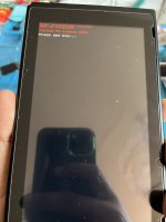
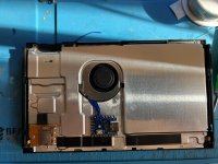
Well, today I do mi first picofly installation and everything works fine, except when I try to lunch EMMC partition

What I do wrong?

actually cannot enter to OFW to

i soldered the 3 47 ohms resistors in the CLK, DAT0 and CMD points.
 

Attachments

  • IMG_5242.jpeg
    IMG_5242.jpeg
    1.4 MB · Views: 41
  • IMG_5237.jpeg
    IMG_5237.jpeg
    3.2 MB · Views: 41

cowboy619

Well-Known Member
Member
Joined
Jan 22, 2014
Messages
248
Trophies
1
Age
40
Location
Cape Town, Western Cape
XP
1,810
Country
Well, today I do mi first picofly installation and everything works fine, except when I try to lunch EMMC partition

What I do wrong?

actually cannot enter to OFW to

i soldered the 3 47 ohms resistors in the CLK, DAT0 and CMD points.

You need to run the unlock.bin but backup boot0 first


Sent from my iPhone using Tapatalk
 

FreeLander

Well-Known Member
Member
Joined
Apr 6, 2023
Messages
350
Trophies
0
Age
35
XP
467
Country
United States
u flash the rp2040 after u should get a succes color after u draged the required files in the rp2040 folder that appers and if u get green after flashing it it means u need to set rgb mode , if u get red u dont need to set rgb mode
Hello. Thanks for explaining this, but I'm a little confused with the red led part. After flashing the firmware and plugging my rp2040, I get a blue light then a purple light, no red. Am I okey with this?

I will install it tomorrow, Waiting for my flex cable :)
 

JackFrostSMT

Well-Known Member
Member
Joined
Jan 18, 2017
Messages
102
Trophies
0
Age
28
XP
270
Country
United States
Hello. Thanks for explaining this, but I'm a little confused with the red led part. After flashing the firmware and plugging my rp2040, I get a blue light then a purple light, no red. Am I okey with this?

I will install it tomorrow, Waiting for my flex cable :)
Replugging might not have the same effect. You should be getting either a green or red led RIGHT after you program.
 

Dandan0404

Well-Known Member
Member
Joined
Mar 25, 2023
Messages
131
Trophies
0
Age
23
XP
183
Country
Philippines
Hello nothing installed yet and did some backreading. I know its necessary for 47ohm resistor. But is it necessary for 20K ohm resistor for RST pin? I have smd 20k lying around is it bad to attach assuming everything is fine?
 

JackFrostSMT

Well-Known Member
Member
Joined
Jan 18, 2017
Messages
102
Trophies
0
Age
28
XP
270
Country
United States
Hello nothing installed yet and did some backreading. I know its necessary for 47ohm resistor. But is it necessary for 20K ohm resistor for RST pin? I have smd 20k lying around is it bad to attach assuming everything is fine?
20k on rst is only needed if you have blue then green success glitching but reset right after. So if you have no problems booting then you don't need it.
 

FreeLander

Well-Known Member
Member
Joined
Apr 6, 2023
Messages
350
Trophies
0
Age
35
XP
467
Country
United States
Replugging might not have the same effect. You should be getting either a green or red led RIGHT after you program.
That's right. I tried it again and got a red led. However, I did not understand what Dee87 said about the red led not needing RGB while green does:
after u draged the required files in the rp2040 folder that appers and if u get green after flashing it it means u need to set rgb mode , if u get red u dont need to set rgb mode

I got a red color right after programming. When replugging I get a blue then white. I asked for advice here and Redius recommended I set RGB jumper, when I did that. Now I get a blue and then purple when plugging.
Post automatically merged:

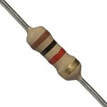
I'm sorry if this a silly question, but will a 47ohms carbon resistor work? They don't sell SMDs in my local store
 

Attachments

  • 311bGhoaiPL._SX342_.jpg
    311bGhoaiPL._SX342_.jpg
    6.4 KB · Views: 54

JackFrostSMT

Well-Known Member
Member
Joined
Jan 18, 2017
Messages
102
Trophies
0
Age
28
XP
270
Country
United States
That's right. I tried it again and got a red led. However, I did not understand what Dee87 said about the red led not needing RGB while green does:


I got a red color right after programming. When replugging I get a blue then white. I asked for advice here and Redius recommended I set RGB jumper, when I did that. Now I get a blue and then purple when plugging.
Post automatically merged:

I'm sorry if this a silly question, but will a 47ohms carbon resistor work? They don't sell SMDs in my local store
If you get red led after programming then do not touch the rgb jumper.

47ohm THT resistor will technically work, but its likely going to be too big to close the console up and I've heard there can be electrical interference with those as they have much more mass than smd resistors.
 
  • Like
Reactions: FreeLander

FreeLander

Well-Known Member
Member
Joined
Apr 6, 2023
Messages
350
Trophies
0
Age
35
XP
467
Country
United States
If you get red led after programming then do not touch the rgb jumper.

47ohm THT resistor will technically work, but its likely going to be too big to close the console up and I've heard there can be electrical interference with those as they have much more mass than smd resistors.
Got it. Thank you!
 

Zeroday

Member
Newcomer
Joined
Apr 7, 2023
Messages
8
Trophies
0
XP
53
Country
Canada
I am getting some odd behavior on my V2..

Install seems to work fine on fw 2.6 (had to do RGB jumper), loaded latests HATs pack onto SD card

Booted in Hekate back up boot0/1, keys, nand

1. I can't boot into OFW, after nintendo screen it goes to what into some loading screen for 5-10 seconds then reboots
2. If I launch into CFW using EMUMMC I can't log into wifi
3. If I launch into CFW using SYSNAND wifi works fine

Card is 64gb fat32, EMUMMC is partition, sys fw is 16

When I disconnected the rp2040 the system boots fine.
 

Contra8bit

Member
Newcomer
Joined
Mar 22, 2023
Messages
10
Trophies
0
Age
36
XP
67
Country
Russia
Hello. I'd like to thank the devs for this great job. One question if I may: When I flashed my rp2040 and re-plugged it. It gives a blue light then white, I saw a video on YouTube where it shows a purple color, not white. Am I good or is there something wrong? Video attached, Thanks.

need to set RGB jumper

I have few rp2040 zero chips.
On one of them LED works from beginning - red after firmware 2.6 and blue > purple after connecting to PC.
On other there no LED at all. When I set RGB bridge, LED works but with different color - green after firmware and blue > cyan (white?) after PC connecting.
So I set RGB bridge to another and colors change like on 2nd chip
So I think it's absolutely normal
 
  • Like
Reactions: FreeLander

Kiuxn

Well-Known Member
Newcomer
Joined
Mar 18, 2023
Messages
61
Trophies
0
Age
27
XP
136
Country
China
I have a question, V2.6. Remove PR2040, OFW cannot start normally, and everything is normal after installing pr2040. Try to restore clean boot0, which is invalid.
When I disconnected the rp2040, the system started abnormally.
 
Last edited by Kiuxn,

FreeLander

Well-Known Member
Member
Joined
Apr 6, 2023
Messages
350
Trophies
0
Age
35
XP
467
Country
United States
I have few rp2040 zero chips.
On one of them LED works from beginning - red after firmware 2.6 and blue > purple after connecting to PC.
On other there no LED at all. When I set RGB bridge, LED works but with different color - green after firmware and blue > cyan (white?) after PC connecting.
So I set RGB bridge to another and colors change like on 2nd chip
So I think it's absolutely normal
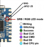
Interesting. your 2nd chip sounds just like mine. Please explain what do you mean by " set RBG to another" ? Did you bridge different points from this diagram?
 

Attachments

  • Screen Shot 2023-04-07 at 7.55.16 AM.png
    Screen Shot 2023-04-07 at 7.55.16 AM.png
    714.2 KB · Views: 73

Site & Scene News

Popular threads in this forum

General chit-chat
Help Users
  • No one is chatting at the moment.
    SylverReZ @ SylverReZ: @E1ite007, I just found this randomly.