Hacking Hardware Picofly - a HWFLY switch modchip

nico77

Well-Known Member
Member
Joined
Apr 6, 2023
Messages
160
Trophies
0
Age
33
XP
238
Country
Indonesia
Well it's done, with huge success.

First picofly install for testing in my own switch lite. I preferred make myself the mosfet glitcher. The soldering process is painful, same in microscope.


I was in doubt if was better start the installation test in my v2 or lite. How is basically for learning, I guess the micropoints solders of lite are a good teacher about difficulty with micro soldering. Next phase is try a oled installation from zero, included homemade mosfet glitcher

I confess: the micropoints of switch lite board for clock/cmd/dat0/ dive me in a frequent conspiracy about shortcut. I was made the soldering points near of 20 times, to certificate about the things are completely well done.
congrats:toot::grog:
those mosfets soo tiny yep
i give up with 8342 hehehe, frikin tiny for me.

I've just finished my picofly installation. Now im struggling at this screen. What should i do next? Or where i can find some guides? i have 128gb samsung microsd card and have no idea to do with it.
congrats:grog::toot::switch:
 

s4n0suk3

Member
Newcomer
Joined
May 8, 2023
Messages
9
Trophies
0
Age
38
XP
70
Country
Venezuela
hi everyone i still having problems with my pico install, tried with anoter rp2040 and again (first time blue, white, them cyan) and now only blue then cyan. checked like @Phantomas77 tell me and i had 15ohms between drain and source here some pics of my mosfet install if anyone see any problem
 

Attachments

  • Photo20230513075800431.jpg
    Photo20230513075800431.jpg
    111.3 KB · Views: 30
  • Photo20230513075816165.jpg
    Photo20230513075816165.jpg
    110.7 KB · Views: 25
  • Photo20230513075838467.jpg
    Photo20230513075838467.jpg
    119.8 KB · Views: 31
  • Photo20230513075845175.jpg
    Photo20230513075845175.jpg
    140.8 KB · Views: 29
  • Photo20230513075850136.jpg
    Photo20230513075850136.jpg
    122.7 KB · Views: 24
  • Photo20230513075856374.jpg
    Photo20230513075856374.jpg
    104.3 KB · Views: 25

jordanbearbear

New Member
Newbie
Joined
May 13, 2023
Messages
4
Trophies
0
Age
23
XP
13
Country
Singapore
Hi, I tried doing the Picofly mod earlier today on the switch lite. Anyways it didn't go well (I kept getting a blue light then a bad CLK/CMD). I tried to undo the mod but I accidentally damaged the ribbon cable (doesn't look very badly damaged). The main question is my switch lite does not turn on now. But when it has the RP 2040 connected to the 3.3v and Ground there is light on the RP 2040 when the power button is pressed. Any idea what could be the issue?

I have bought a replacement ribbon cable from the main board to the left joystick board (waiting for delivery) but is that the issue? or could it be something else? Thanks
 
Last edited by jordanbearbear,

Phantomas77

Well-Known Member
Member
Joined
Dec 19, 2022
Messages
285
Trophies
0
XP
732
Country
Italy
hi everyone i still having problems with my pico install, tried with anoter rp2040 and again (first time blue, white, them cyan) and now only blue then cyan. checked like @Phantomas77 tell me and i had 15ohms between drain and source here some pics of my mosfet install if anyone see any problem
Ok, so lets recap, which console version is this?
You're using what looks 2xIRFHS8342, the resistance between S&D when soldered is good, verify as well that there're no shorts between Gate and GND.
The resistors are 47 Ohms on the DAT0, CLK and CMD line?
From where are you sourcing the +3.3V? If it's not the same point as in the AIO guide's diagram, that's the problem.

The solder point in the pic below looks sketchy, like it's a cold joint on Drain pin and soldered together to Source wire. Tin it again and ensure the wires are isolated and not touching.
Post automatically merged:

Will this Wire Work for mosfet?. It is a AWG 30 (0.25mm).
It's perfect for the Source and Drain, for Gate you can use a thinner enamel wire

I use as well AWG30 for GND and +3.3V.
 

Attachments

  • Photo20230513075838467__01.jpg
    Photo20230513075838467__01.jpg
    66.1 KB · Views: 34

s4n0suk3

Member
Newcomer
Joined
May 8, 2023
Messages
9
Trophies
0
Age
38
XP
70
Country
Venezuela
Ok, so lets recap, which console version is this?
You're using what looks 2xIRFHS8342, the resistance between S&D when soldered is good, verify as well that there're no shorts between Gate and GND.
The resistors are 47 Ohms on the DAT0, CLK and CMD line?
From where are you sourcing the +3.3V? If it's not the same point as in the AIO guide's diagram, that's the problem.

The solder point in the pic below looks sketchy, like it's a cold joint on Drain pin and soldered together to Source wire. Tin it again and ensure the wires are isolated and not touching.
Post automatically merged:


It's perfect for the Source and Drain, for Gate you can use a thinner enamel wire

I use as well AWG30 for GND and +3.3V.
mine is switch v2 using 47 ohms resistor ok will try again thanks for quick response
 

QuiTim

Well-Known Member
Member
Joined
Mar 30, 2023
Messages
757
Trophies
0
XP
1,178
Country
Albania
Thx for the info. Could you let me know what are these resistors I have to replace? I have this board on hand. Thank you!
Something like this (just dont forget to bridge the points of the resistors once you remove them):
Or you could resolder 0201 47ohm resistors and replace the existing ones (which are 470ohm) in the same spot
 

Attachments

  • RP2040-Tiny-Kit-details-3-2.jpg
    RP2040-Tiny-Kit-details-3-2.jpg
    32 KB · Views: 38
Last edited by QuiTim,

jam_tac_cool

New Member
Newbie
Joined
May 13, 2023
Messages
4
Trophies
0
Age
35
XP
32
Country
Canada
Something like this (just dont forget to bridge the points of the resistors once you remove them):
Or you could resolder 0201 47ohm resistors and replace the existing ones (which are 470ohm) in the same spot
Works like a charm!
 

Attachments

  • IMG_1257.jpeg
    IMG_1257.jpeg
    3.3 MB · Views: 34
  • IMG_1258.jpeg
    IMG_1258.jpeg
    2.1 MB · Views: 31

chronoss

Well-Known Member
Member
Joined
May 26, 2015
Messages
3,010
Trophies
1
XP
4,917
Country
Congo, Republic of the
Hi !!!

Just to know, i can reset my Switch with Picofly installed ?
I need to reset it to erase all account inside...
Thanks a lot !!!
 

jam_tac_cool

New Member
Newbie
Joined
May 13, 2023
Messages
4
Trophies
0
Age
35
XP
32
Country
Canada
btw how the RP2040 Tiny fit with the metal heatshield??

View attachment 371141

is it fit perfectly ?
since the RP2040 zero need to remove port usb-C
how is it compare to RP2040 Tiny ?
It fits pretty well under the heat shield. I used double-sided tape to place the Tiny on the EMMC shield below the heat shield. The Tiny has a low-profile FPC connector connected to a USB adapter board(it contains USB TYPE-C female socket, FPC connector, Boot, and Reset button). Also, the backside of the Tiny board is a flat surface.
 

nico77

Well-Known Member
Member
Joined
Apr 6, 2023
Messages
160
Trophies
0
Age
33
XP
238
Country
Indonesia
It fits pretty well under the heat shield. I used double-sided tape to place the Tiny on the EMMC shield below the heat shield. The Tiny has a low-profile FPC connector connected to a USB adapter board(it contains USB TYPE-C female socket, FPC connector, Boot, and Reset button). Also, the backside of the Tiny board is a flat surface.
nice:yay:

tiny gonna look perfect when installed.

did you use RP2040 zero before ?
or instantly use the RP2040 Tiny ?
 

swichitup

Member
Newcomer
Joined
Mar 26, 2023
Messages
7
Trophies
0
Age
43
XP
82
Country
United Kingdom
I have a supplier at the moment supplying lite motherboard with Pico fitted for £110 UK only and also through eBay so PayPal can be used for safety.

PM me if anyone is interested
 

lightninjay

Well-Known Member
Member
Joined
Mar 28, 2023
Messages
560
Trophies
0
Age
31
XP
1,392
Country
United States
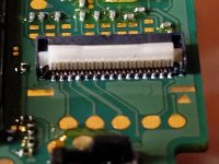
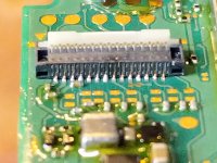
Just finished up my fourth picofly install, third switch lite. Technically this mod was done before the second switch lite, but I mangled the daughterboard connector from opening and closing it too much.

Thankfully, the connectors are available online from parts repair stores, so I ordered two and attempted the replacement myself with a lot of flux, a hot-air station, and at the recommendation of a youtube video I watched, I heated the bottom of the board to remove the connector and place the new one. I didn't get super large solder blobbing on every single pin, but she boots with a live and working screen plus touch and left joycon control!

I have a few more switches in the pipeline for friends that I plan to mod with picofly, but it will be a little before that happens. The next install is likely going to be a roadtrip with my tools to a friends', to perform an install in his living room with him present lol.

Frontside of the connector after replacement
IMG_20230513_181829.jpg

Backside of the connector after replacement
IMG_20230513_181811.jpg
 

malgamer

Well-Known Member
Newcomer
Joined
May 8, 2022
Messages
85
Trophies
0
Age
46
Location
malaysia
XP
455
Country
Malaysia
Hi guys.
Is it normal the boot take about 10s glitchin sometimes?

Actually I ch
Hi guys.
Is it normal the boot take about 10s glitchin sometimes?

Actually I changed the wires. Using AWG38 for RST, CLK, DAT and CMD. Others using AWG30
it is normal if your emmc toshiba and skyhynix
anged the wires. Using AWG38 for RST, CLK, DAT and CMD. Others using AWG30your
 

jordanbearbear

New Member
Newbie
Joined
May 13, 2023
Messages
4
Trophies
0
Age
23
XP
13
Country
Singapore
Just finished up my fourth picofly install, third switch lite. Technically this mod was done before the second switch lite, but I mangled the daughterboard connector from opening and closing it too much.

Thankfully, the connectors are available online from parts repair stores, so I ordered two and attempted the replacement myself with a lot of flux, a hot-air station, and at the recommendation of a youtube video I watched, I heated the bottom of the board to remove the connector and place the new one. I didn't get super large solder blobbing on every single pin, but she boots with a live and working screen plus touch and left joycon control!

I have a few more switches in the pipeline for friends that I plan to mod with picofly, but it will be a little before that happens. The next install is likely going to be a roadtrip with my tools to a friends', to perform an install in his living room with him present lol.

Frontside of the connector after replacement
View attachment 371184

Backside of the connector after replacement
View attachment 371183
Sorry to bother you, is it possible to check with you what the daughter board does?

I accidentally damaged the ribbon cable from the main board to the daughter board. Now my switch lite does not turn on. (No sound, no display, nth) But the motherboard shows power when I press the power button @ 3.3v pt.
(Tested this with the picofly)

Could that ribbon cable to the daughter board be the issue or it is smt else?
 

Site & Scene News

Popular threads in this forum

General chit-chat
Help Users
    K3Nv2 @ K3Nv2: 80 for us all that rain then mother nature's like have some sun burn