Hacking Hardware Picofly - a HWFLY switch modchip

tsukimaru

Well-Known Member
Newcomer
Joined
May 3, 2023
Messages
51
Trophies
0
Age
29
XP
126
Country
Nicaragua
you probably need reflow your apu
I doubt that. I had the same result with a V2 yesterday and sadly I got the same BSOD and proceeded to reflow it to no avail.
Post automatically merged:

i'll try to resolder them, shall i dm you the results later?

Sure thing buddy. Make sure the solder points look round and symetrical. That way you'll know you have a solid connection
 

DaoudMalek

Member
Newcomer
Joined
Dec 13, 2019
Messages
11
Trophies
0
Age
25
XP
63
Country
United States
Disregarding the blurry photo (maybe clean your camera lens), it looks like you could do with a little more flux/less time with the soldering iron stuck in the pool of solder. Your soldering points should be shiny when soldered correctly. When they are dull (like in your photo) it's usually an indication that you should use more flux.

EDIT:

I was half a second too slow lol
that's fine, thanks a lot for the advice!
Post automatically merged:

I doubt that. I had the same result with a V2 yesterday and sadly I got the same BSOD and proceeded to reflow it to no avail.
Post automatically merged:


Sure thing buddy. Make sure the solder points look round and symetrical. That way you'll know you have a solid connection
im afraid i'll have trouble putting the resistors back, i don't have a microscope and my tweezers suck. should i wait until i buy better equipment?
 

WyzeGye

New Member
Newbie
Joined
May 29, 2017
Messages
1
Trophies
0
Age
37
XP
57
Country
Canada
Any tips for the 3 smallest points on the switch lite? Don't have the diagram handy, but the cluster including Dat0 above the apu and to the left of RST.

For the life of me I can't get them tinned well, let alone soldered. I am not good but managed well enough with the rest.

Already brought the system into the local cell repair shop and they're refusing the work, so it's all me.

Good flux. 30awg enameled wire. Tiny tip, though have been having better results with a larger tapered tip. Microscope too. Everything points to skill issue.

I've settled on getting one of the 3 points done per day, but don't have much faith in myself to get even that done.
 

lightninjay

Well-Known Member
Member
Joined
Mar 28, 2023
Messages
560
Trophies
0
Age
31
XP
1,375
Country
United States
that's fine, thanks a lot for the advice!
Post automatically merged:


im afraid i'll have trouble putting the resistors back, i don't have a microscope and my tweezers suck. should i wait until i buy better equipment?
It will make the job exponentially easier with the right equipment. Don't rush these kinds of mods, do them right and they will work the first time, and keep working for you.
Post automatically merged:

Any tips for the 3 smallest points on the switch lite? Don't have the diagram handy, but the cluster including Dat0 above the apu and to the left of RST.

For the life of me I can't get them tinned well, let alone soldered. I am not good but managed well enough with the rest.

Already brought the system into the local cell repair shop and they're refusing the work, so it's all me.

Good flux. 30awg enameled wire. Tiny tip, though have been having better results with a larger tapered tip.

I've settled on getting one of the 3 points done per day, but don't have much faith in myself to get even that done.
Do as I did in my message here, click the little arrow at the top of the quote box (next to my name) and it will take you to the post where all the photos are displayed.
I figured I would document my process of how I approached soldering in the tiny and tight areas of the switch lite, along with the close proximity of the pads to each other.

The main philosophy was "if it can be masked with Kapton during soldering, DO IT. Then flux it, solder it, clean it, and cover it in UV-cure resin."

This seemed to be pretty effective, and my only issues were this being my first flex install, I had to make sure I had good contact on the caps and no bridging.

View attachment 365360
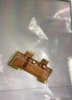
Here's my V2 flex cable secured to a piece of lumber with electrical tape and kapton to do the finer masking.
View attachment 365361
It tinned easily, and soldered easily without worrying about bridging to the side pins.
View attachment 365366
Then I cleaned it, demasked it, and covered it in resin.
View attachment 365363
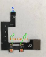
Here is the Lite's 3.3v points as called out by the definitive guide. I masked off the small component nearest them with Kapton, tinned the pads...
View attachment 365364
soldered my 30awg Kynar to it...
View attachment 365365
and then also covered it in resin!
View attachment 365367
This is the GND point that has been masked off and soldered to.
View attachment 365368
Here is the RST point (I opted for a single pad since I'm using 40awg magnet wire)
View attachment 365369
Here's that RST point covered in yet more resin
View attachment 365370
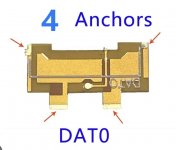
Masking off and tinning the DAT0 made things much simpler
View attachment 365371
Here's CMD masked out and tinned
View attachment 365372
and here's DAT0, CMD, and CLK all soldered in and resin'd
View attachment 365362
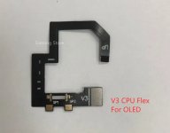
here's the flex pre-tinned
View attachment 365373
This was one of my first attempts at soldering the flex (possibly the very first) but ultimately I got it all cleaned up and functioning properly.

So I learned that doing a switch lite is slightly more difficult than doing a full-size switch, but with the right approach it doesn't have to be impossible or terrifying.

Also, fun side-note, be very careful when trying to remove the battery connector on the switch lite, because you have to disturb a jumper cable that runs the front LCD. If any of these traces are interrupted, you will have to trace which ones have lost continuity and bridge the appropriate pins with magnet wire (ask me how I know)

The short and sweet of it, is that my household now has two hacked switches (which is a 100% success rate on 100% of the consoles in the house) and I feel more confident in my micro-soldering skills :D
 

DaoudMalek

Member
Newcomer
Joined
Dec 13, 2019
Messages
11
Trophies
0
Age
25
XP
63
Country
United States
It will make the job exponentially easier with the right equipment. Don't rush these kinds of mods, do them right and they will work the first time, and keep working for you.
Im already planning to buy some quality equipment soon, it's just that i got the resistors today and wanted to practice on the rp 2040 as i don't mind replacing it
 
  • Like
Reactions: lightninjay

tsukimaru

Well-Known Member
Newcomer
Joined
May 3, 2023
Messages
51
Trophies
0
Age
29
XP
126
Country
Nicaragua
that's fine, thanks a lot for the advice!
Post automatically merged:


im afraid i'll have trouble putting the resistors back, i don't have a microscope and my tweezers suck. should i wait until i buy better equipment?

By my experience, if you don't have the right tools, it's usually a bad idea to continue. Get the proper tweezers, get a microscope (I use a cheap one that gets the job done, doesn't have to be anything fancy) and get your hands dirty. The only way to improve is to do it many many times.
Post automatically merged:

Well, I found it on my desk, check it. Again, I'm extra careful with these installations but the only different thing I did this time is only using a single mosfet, bit I've successfully done it in Te past. Hopefully now you see why I'm so confused
Post automatically merged:

And another thing worth mentioning is that I've already performed a reflow on my APU and no luck so far. I'm super frustrated since this is the first install in over a week that dies like this
Btw sorry for insisting, but I'm quite baffled by this dead switch. I killed 2 prior to this one and those were 100% a bad installation due to the RST point having a transistor next to it and I think I fried the transistor both times but that should've been avoided with the eMMC solder points.

It has worked multiple times in the past but this time it simply... died, no reason to point at and that scares me :s
 
Last edited by tsukimaru,
  • Like
Reactions: DaoudMalek

LogicalMadness

Well-Known Member
Member
Joined
Nov 3, 2014
Messages
287
Trophies
0
Age
41
XP
690
Country
United States
Looks like I didn't make any ASSes with my ASSumption of an ASSessment... THIS time ;P

I wasn't referring to you, I was just saying.

So I'm not trustworthy enough for u wooooow bro :-(

Looking back, I was really only referring to @rehius actually. Poorly phrased but doesn't reflect on you until YOU make it so.

Here maybe this will satisfy your ego:

FOR ANYONE READING HERE - I've been streaming my mods for just over a month now, I know this because it all started with an OLED that I'm still working on. In the meantime, I've completed many other installs though. Throughout that whole time, @Dee87 has been my wingman and made countless advisements. Now, looking back, 95% of what felt like nagging from him, turned out to be the way I prefer doing things anyway (I'm a stubborn a-hole who MUST do things my own way).

Take away:

If @Dee87 takes the time to advise you, take a more serious listen to him than you otherwise would, IMO.
 
  • Love
Reactions: QuiTim

Dee87

Well-Known Member
Member
Joined
Mar 19, 2023
Messages
1,139
Trophies
1
XP
1,578
Country
Germany
I wasn't referring to you, I was just saying.


Looking back, I was really only referring to @rehius actually. Poorly phrased but doesn't reflect on you until YOU make it so.

Here maybe this will satisfy your ego:

FOR ANYONE READING HERE - I've been streaming my mods for just over a month now, I know this because it all started with an OLED that I'm still working on. In the meantime, I've completed many other installs though. Throughout that whole time, @Dee87 has been my wingman and made countless advisements. Now, looking back, 95% of what felt like nagging from him, turned out to be the way I prefer doing things anyway (I'm a stubborn a-hole who MUST do things my own way).

Take away:

If @Dee87 takes the time to advise you, take a more serious listen to him than you otherwise would, IMO.


Hahahaha bro that must been so hard for u to say Xd

But I'm not always right (correct) , and people who dont like to "listen" or take advise from someone else need to learn the "hard" way like "u"

its just i tried alot of different thing and ways of installing them and had the best outcomes no issues when i do it the way i always tell everyone to do it :-)
 
Last edited by Dee87,

deeps

Well-Known Member
Member
Joined
Jul 3, 2007
Messages
451
Trophies
1
XP
1,250
Country
I would assume since he only mentions single mosfet installs, it means those single mosfets are run to both caps.

I've done 12 switches with picofly so far, all with single mosfet to single cap and they all work fine. 0.2mm wires at about 17mm length. One of them glitches a bit slower though (3-30 seconds), so I guess the SDA/SCL thingy could be useful there. But in general I'd say single mosfet to single cap is enough.
 

AntonIX

Active Member
Newcomer
Joined
Jan 14, 2023
Messages
34
Trophies
0
Age
23
Website
devpins.org
XP
207
Country
Russia
@rehius Are you 100% sure that this capacitor can be used on cpu. Seems like my erista died. No reaction to power button
 

Attachments

  • capacitor.jpg
    capacitor.jpg
    164 KB · Views: 30
  • Like
Reactions: Danook28

abal1000x

Well-Known Member
Member
Joined
Jun 5, 2022
Messages
1,063
Trophies
0
XP
1,373
Country
Gaza Strip
By my experience, if you don't have the right tools, it's usually a bad idea to continue. Get the proper tweezers, get a microscope (I use a cheap one that gets the job done, doesn't have to be anything fancy) and get your hands dirty. The only way to improve is to do it many many times.
Post automatically merged:


Btw sorry for insisting, but I'm quite baffled by this dead switch. I killed 2 prior to this one and those were 100% a bad installation due to the RST point having a transistor next to it and I think I fried the transistor both times but that should've been avoided with the eMMC solder points.

It has worked multiple times in the past but this time it simply... died, no reason to point at and that scares me :s
What i am afraid when you got BSOD, its not the mosfet. Usually people extra careful in installing the mosfet, but neglected the D0/CMD/CLK. Those 3 goes directly to the APU. So don't neglect or wrongly put those little resistor 4R7. Maybe you use a different resistor?

CMD
lite_cmd.png


DAT0
lite_dat0.png


CLK
lite_clk.png

Post automatically merged:

@rehius Are you 100% sure that this capacitor can be used on cpu. Seems like my erista died. No reaction to power button
I remember saving these on my note (from this thread, try to search it)

apu_cap_replace_from_rp2040_zero.jpeg
 
Last edited by abal1000x,
  • Like
Reactions: Phantomas77

lightninjay

Well-Known Member
Member
Joined
Mar 28, 2023
Messages
560
Trophies
0
Age
31
XP
1,375
Country
United States
I've done 12 switches with picofly so far, all with single mosfet to single cap and they all work fine. 0.2mm wires at about 17mm length. One of them glitches a bit slower though (3-30 seconds), so I guess the SDA/SCL thingy could be useful there. But in general I'd say single mosfet to single cap is enough.
As a matter of fact, my very first install on my own switch, I mangled the left capacitors pads, and only had the availability of using the right side capacitor with a single mosfet, and it glitches just fine (V1 patched).

I am merely repeating the suggestion of the firmware dev, Rehius, that doing such things can be a helpful redundancy, which can save time later, trying to troubleshoot.
 
  • Like
Reactions: Dee87

Moromoromoro

Member
Newcomer
Joined
May 18, 2023
Messages
7
Trophies
0
Age
29
XP
193
Country
United Kingdom
Is seen pictures using v1 cable on v2 switch but are there any pictures of using v2 cable on v1v i do believe the bigger connection is the feed and smaller is ground but want to confirm with a picture if someone has one would much appreciate
 

LogicalMadness

Well-Known Member
Member
Joined
Nov 3, 2014
Messages
287
Trophies
0
Age
41
XP
690
Country
United States
Hahahaha bro that must been so hard for u to say Xd

But I'm not always right (correct) , and people who dont like to "listen" or take advise from someone else need to learn the "hard" way like "u"

its just i tried alot of different thing and ways of installing them and had the best outcomes no issues when i do it the way i always tell everyone to do it :-)

No, I try not to say something unless I fully believe it. Honesty is always easy for me to say. I left wiggle-room in my statement for you to be wrong ;)

It being "the hard way" is just your opinion, though. Just like you, I enjoy exploring ALL the ways something CAN be done so I KNOW how I can be most efficient later. I love all the small lessons I learned along the way, from you AND from my 'mistakes'.

You don't know, til you know, ya know?
 

QuiTim

Well-Known Member
Member
Joined
Mar 30, 2023
Messages
756
Trophies
0
XP
1,162
Country
Albania
Is seen pictures using v1 cable on v2 switch but are there any pictures of using v2 cable on v1v i do believe the bigger connection is the feed and smaller is ground but want to confirm with a picture if someone has one would much appreciate
This should work
*Edit: updated the picture with correct number of capacitors. The installation remains the same.
 

Attachments

  • -1909896910-1498365690.jpg
    -1909896910-1498365690.jpg
    51.6 KB · Views: 35
Last edited by QuiTim,

Danook28

Well-Known Member
Member
Joined
Jul 17, 2018
Messages
497
Trophies
0
Age
34
XP
1,036
Country
Oman
With this and pico and 47R can hack my nintendo oled. 3v Flex and adapter dat0. I have this stuff now!!!!
 

Attachments

  • 27597591-1620749110.jpg
    27597591-1620749110.jpg
    131.3 KB · Views: 28
  • -759955711058556785.jpg
    -759955711058556785.jpg
    86.4 KB · Views: 25

QuiTim

Well-Known Member
Member
Joined
Mar 30, 2023
Messages
756
Trophies
0
XP
1,162
Country
Albania
With this and pico and 47R can hack my nintendo oled. 3v Flex and adapter dat0. I have this stuff now!!!!
You can but be aware that this dat0 adapter is not very good. Some people (including myself) have had problems with it.
It seems that the tiny exposed copper part that goes under the emmc is a bit too big and alot of times makes contact not just with dat0 line/solder ball but with another one close to it as well (so in a way it creates a short under emmc)
You can give it a try, maybe it works for you, but just to be safe for the future order the "4 anchor" model which everyone says it's ok.
 

Attachments

  • Screenshot_20230518_204336_Samsung Internet.jpg
    Screenshot_20230518_204336_Samsung Internet.jpg
    185.4 KB · Views: 28

tsukimaru

Well-Known Member
Newcomer
Joined
May 3, 2023
Messages
51
Trophies
0
Age
29
XP
126
Country
Nicaragua
What i am afraid when you got BSOD, its not the mosfet. Usually people extra careful in installing the mosfet, but neglected the D0/CMD/CLK. Those 3 goes directly to the APU. So don't neglect or wrongly put those little resistor 4R7. Maybe you use a different resistor?

CMD
View attachment 372223


DAT0
View attachment 372224

CLK
View attachment 372225
Post automatically merged:


I remember saving these on my note (from this thread, try to search it)

View attachment 372228
It's funny that you mention that since the reason I killed the previous two V2 switches was because of my RST point since that was the only variable between V1 patched and V2 MARIKO since MARIKO has a transistor next to the point and I believe the heat killed it somehow.

I changed my installation layout to mostly use the eMMc points and I've seen incredible reliability using those, but this latest one just farted for no apparent reason.

I wished I had trouble installing it so that way I could just blame myself for a crappy installation but I made sure it was donde properly. Double/triple checked everything under the microscope during/after I was working but the BSOD was like a slap to the face :s

I just want to know how to avoid it as I'm having to replace every single board I kill and I'm running out of replacements :s
 
  • Like
Reactions: abal1000x

aspirins

Member
Newcomer
Joined
May 11, 2023
Messages
10
Trophies
0
Age
39
XP
56
Country
Belarus
hi, help switch lite instal picofly, start only hekate, emmc info - Failed to init, full stock loading only violet display
 

Site & Scene News

Popular threads in this forum

General chit-chat
Help Users
    K3Nv2 @ K3Nv2: Honey turkey sandwhich +1