- Joined
- Jan 22, 2014
- Messages
- 248
- Trophies
- 1
- Age
- 40
- Location
- Cape Town, Western Cape
- XP
- 1,810
- Country

Just curious, would this chip work on the latest TOTK OLED model?
Yes all oleds are the same
Sent from my iPhone using Tapatalk
Just curious, would this chip work on the latest TOTK OLED model?

Sxcore cable. Interesting information. This is my first mod using a recicled ( but new) v2 cable. The others I used my own mosfet mount.Seems issue with the voltage. When the logo shows up especially the joycon logo, the voltage of the cap inside the apu (which connected to the mosfet) will be decreased, from around 2V, to around 1V then stopped at 0.643V.
Do you use mosfets or hwfly flex cable?
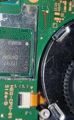
Its that cmd oled?Hey, i accidentially ripped these pads off, are there any alternative solder points for that? Thanks!
I have installed in 10 of those without problemJust curious, would this chip work on the latest TOTK OLED model?
Sorry, yesIts that cmd oled?
What do you sell these for usually?I have installed in 10 of those without problem
Couples hour ago, people are posting messages about clk alt point which is in the emmc. cmd pin is in the left of clk pin in the emmc.Sorry, yes
Post automatically merged:
What do you sell these for usually?
UffAround 1 am today, people are posting messages about clk alt point which is in the emmc. cmd pin is in the left of clk pin in the emmc.
View attachment 373718
") Thanks, i will sell it then, gave up on it already anyway
Thanks, i will sell it then, gave up on it already anywayA suggestion, if I may: you can use main/extra GND from the points where the SD card shield is soldered, no need to run long wires.@Zm1231 The new firmware have a better debugging. If it is easy to upload the flash, you might try it.
Post automatically merged:
Thank you @rehius and everyone in here, another lite modded.
View attachment 373685
Using 51ohm on CMD/CLD/Dat0, hwfly flex v2 and using 2 gnd as precaution.
Guys if i want to factory reset, is it from hekate or from ofw?
This member is explaining why blue screen happens after modding some OLEDs. The theory is the dat0 adaptor is touching other points. I did get a blue screen on OLED and the dat0 adaptor was not fixed in place, this makes sense to me.I think that when i put the qsb it was not exactly on the dat0 point but in between dat0 ball and the next ball, making a short circuit, wierdly it turned on first time but never did after that.... you should be able to unbrick it, chaging the EMMC and making a new nand using donor nand BUT this is only if you took your prod.key, you should be able to put a new EMMC and load hekate in any case to get the prod.keys
For the next ones if you are able to reball that's the best, if you use a qsb, the orange oled qsb is the best (for me)
But the most important is when you install the qsb, check the diode value from qsb to ground and it must be in between 400 and 460 or little more (never got above 440~450) and also check diode value from qsb to 3.3v (should be in between 650 and 70)
I lately experiment with the Dat0.This member is explaining why blue screen happens after modding some OLEDs. The theory is the dat0 adaptor is touching other points. I did get a blue screen on OLED and the dat0 adaptor was not fixed in place, this makes sense to me.
How can I prevent this from happening. I didn't get the part where he says check 3v3 diode mode. I'm used to checking it on ground and getting that 0.6v
any input is appreciated on how to make sure the dat0 adaptor is not touching other points.
It's pretty smart to shift it to the left. I'll start doing that.I lately experiment with the Dat0.
I think you better find the datasheet of the nand.
For me its KLMCG4JETD. There the pinout for the emmc.
View attachment 373729
You could see that pin number 2 is NC (Not Connected). So i shift the adapter to the left (to pin number 2) to avoid shorted with pin Dat 1 (pin number 4)
Using diode mode its 0.6 (to GND) when its not Short Circuited with neighbour pin. But will decrease 0.4-0.5 if it is somekind of shorted.
Maybe i am lucky, when SC, i don't meet the bluescreen.
When slightly shorted the value is around 0.4 the picofly throws:
=*== eMMC test failure - read failed
When slightly shorted the value around 0.55-0.57:
The glitch happened, but its glitching forever until timeout.
I repeat this like 3 times, and its the same, glitching until timeout.
=== Glitch attempt limit reached, cannot glitch
The probability of success is good only when the value is slightly above 0.6, like 0.60, 0.61, 0.62.
Maybe different ic type will throws diferent diode value.
In the pcb its shifted to the right.It's pretty smart to shift it to the left. I'll start doing that.
Why? You ripped of a 4,7k ohm resistor. So you should see a purple screen when turning on the switch. Just buy this resistor solder it to and you will be fine. If you can't solder this size get a bigger one with the same resistance and solder it with flywires to the pads. Or let someone else do it for you...Uff
I think that not so hard to fix coz the left and right line is fine can do jumper wier if rip only the one pad. If only resistor that not damge only change with new one. Good look brotherWhy? You ripped of a 4,7k ohm resistor. So you should see a purple screen when turning on the switch. Just buy this resistor solder it to and you will be fine. If you can't solder this size get a bigger one with the same resistance and solder it with flywires to the pads. Or let someone else do it for you...
Thanks for your reply, i took a picture from another post just to show which resistor i am talking about. Its not mine.Why? You ripped of a 4,7k ohm resistor. So you should see a purple screen when turning on the switch. Just buy this resistor solder it to and you will be fine. If you can't solder this size get a bigger one with the same resistance and solder it with flywires to the pads. Or let someone else do it for you...
Once again a nice reminder that you should never be too confident and take your time for such things.Thanks!I think that not so hard to fix coz the left and right line is fine can do jumper wier if rip only the one pad. If only resistor that not damge only change with new one. Good look brother
The RGB/BGR mode is already deprecated. Now the error code is coded by pulse not by color. Read the "led indicator" section in "important post".I have a small doubt about my RP2040-Zero, after flashing i have a yellow light. If i plug it to my computer, i have a blue light. So i don't need to bridge the RGB Mode Jumper, right ?
@Zm1231 The new firmware have a better debugging. If it is easy to upload the flash, you might try it.
Post automatically merged:
Thank you @rehius and everyone in here, another lite modded.
View attachment 373685
Using 51ohm on CMD/CLD/Dat0, hwfly flex v2 and using 2 gnd as precaution.
Guys if i want to factory reset, is it from hekate or from ofw?
Hey, i accidentially ripped these pads off, are there any alternative solder points for that? Thanks!