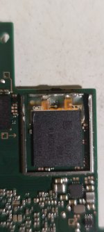
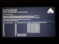
Hi, just performed a picofly install on a Switch OLED w/ one of those chinese boards that come with the FPCBs and am just suffering one small issue. There is a 10-20% chance the Picofly errors with code **= or *=* and then the Switch boots normally into OFW. The rest of the time it boots into hekate/atmosphere no problem. They are eMMC DAT0 errors I believe. I replaced the V5 DAT0 adapter with a corner DAT0 adapter because of this issue but also because on OFW I noticed it would either get stuck at Nintendo (Switch) logo or boot to home screen then crash with error 2002-3539. Once I replaced the DAT0 adapter, the crashing/freezing on OFW stopped but the chip still fails to glitch with those LED errors occasionally. If I let the Switch sit for a few minutes and try booting again it usually works no problem.
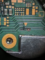
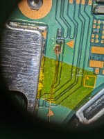
I have a feeling it could be related to DAT0 wire, I have it run the same way most modders do ('under' the gamecard/microSD board direct to the picofly, NOT to the FPCB point) so I purchased better slightly thicker wire for the DAT0. Waiting for it to arrive. I am currently using 38AWG for DAT0 and RST but it seems a little too thin. If nothing else it is probably wise to replace the two wires with 36AWG regardless, i just got a little excited and used what wire I had on me lol.
Anyone else experience any similar LED codes with similar symptoms? I tried searching this thread for the LED codes but the search didn't wanna work for me so I'm gonna try and manually comb thru some pages lol.
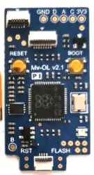
I attached a picture of the picofly board from the ali listing. It looks identical to what I received.
thanks")
I have a feeling it could be related to DAT0 wire, I have it run the same way most modders do ('under' the gamecard/microSD board direct to the picofly, NOT to the FPCB point) so I purchased better slightly thicker wire for the DAT0. Waiting for it to arrive. I am currently using 38AWG for DAT0 and RST but it seems a little too thin. If nothing else it is probably wise to replace the two wires with 36AWG regardless, i just got a little excited and used what wire I had on me lol.
Anyone else experience any similar LED codes with similar symptoms? I tried searching this thread for the LED codes but the search didn't wanna work for me so I'm gonna try and manually comb thru some pages lol.
I attached a picture of the picofly board from the ali listing. It looks identical to what I received.
thanks