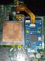
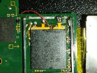
A friend sent these to me. I only tested the adapter on an old HWFLY modchip and its giving me conflicting results. I'm still waiting for my batch of rp2040 tiny to arrive tomorrow or after tomorrow to fully test on a fresh console.
That actually wouldn't matter since the other adapter I made works just fine. The only difference is that this one takes a little longer path. I only connected D0 for diagnostic purpose since I already have the other points soldered in. On this console it boots directly to OFW indicating something is wrong. The reballed eMMC is definitely correct otherwise it wouldn't have booted or at least wouldn't beep on both ends. I will test again with another fresh console once my chips arrives. I honestly don't see why it shouldn't.
Guys I did my first Switch Lite install with the trusty mosfet on the back.
However the glitch is quite slow, rarely taking less than 10 seconds.
Should I go for a double mosfet on the front or just accept that some Lites can be like this? (I hope for the second, lol)
I had an oled that glitched really slowly. anything between 10 seconds to a minute. mosfet on the back. Added another mosfet on the back - no change. Added a mosfet on the apu (so 3 mosfets in total) - still no change. disconnected mosfets on the back and only used the one on apu - boom, 3 second glitch every time.
most other oleds I've done have one on the back and glitch fast every time.
The point of the anecdote is that changing things around can make a difference in unexpected ways.
Guys I did my first Switch Lite install with the trusty mosfet on the back.
However the glitch is quite slow, rarely taking less than 10 seconds.
Should I go for a double mosfet on the front or just accept that some Lites can be like this? (I hope for the second, lol)
Welcome to the dark side of front mount mosfets my brother in arms .
what awg of wire did you use from the mosfet to the cap? From experience ,in this scenario, when i was using 40 awg wire the glitch was quite slow. When i moved to 30 awg it got faster. Its usually around 5-7 seconds glitch, but sometimes it takes 15 seconds. Do keep in mind that the soldering skills also affect the connections and therefore the glitch time.
share some light on me. I succesfully reballed 2 OLEDS (first time doing this,permanent dat0) but they broke (one in 1 month, the other one in 1 week). The 1 week one was fixed with a reflow, but the 1 month one was not fixed with a reflow -i think this one needs a reball.
I dont know what could ve went wrong tbh. I heat the board gradually for 4 minutes untill i reach melting solder temperature. After the chip sat in place, i leave the heat on for 30 more seconds . Then i take the heat off and let it cool.
But im clearly doing something wrong since im having this problem on both consoles.
Ok so. I checked picofly version and i was still on 2.73. I tryed several times more to update, and it finnaly worked.
After attempting to do a new NAND write from scratch with prodinfo, OFW was stuck on logo . So i did a NAND restore to my old NAND save (the one that i was getting 3539 error on ).
Now when trying to start OFW i get this screen View attachment 398276
Well. View attachment 398280
I encountered the same problem after installing picofly, I recreated mmc from the donor nand file. Just remember to write a higher version than your ofw software version
I encountered the same problem after installing picofly, I recreated mmc from the donor nand file. Just remember to write a higher version than your ofw software version
i did a donor nand rebuild . Worked for a couple of days, then it started acting up again.
While acting up i put 200 ohm resistor on DAT0 and 200 ohm on CMD, and i was able to boot OFW with no nand rebuild.
After that i did a Nand rebuild again and its been a couple of days "stress" testing it and so far its ok. But i dont know if this will last.
Oh nevermind im talking about 3539 errors,bootloops and blackscreens on startup. Your experience is probably just a bad HOS on OFW. I just realised.
Welcome to the dark side of front mount mosfets my brother in arms .
what awg of wire did you use from the mosfet to the cap? From experience ,in this scenario, when i was using 40 awg wire the glitch was quite slow. When i moved to 30 awg it got faster. Its usually around 5-7 seconds glitch, but sometimes it takes 15 seconds. Do keep in mind that the soldering skills also affect the connections and therefore the glitch time.
Post automatically merged:
share some light on me. I succesfully reballed 2 OLEDS (first time doing this,permanent dat0) but they broke (one in 1 month, the other one in 1 week). The 1 week one was fixed with a reflow, but the 1 month one was not fixed with a reflow -i think this one needs a reball.
I dont know what could ve went wrong tbh. I heat the board gradually for 4 minutes untill i reach melting solder temperature. After the chip sat in place, i leave the heat on for 30 more seconds . Then i take the heat off and let it cool.
But im clearly doing something wrong since im having this problem on both consoles.
I don't know what technique you use but this is how professionals do it,
After you lift the chip you should apply low melt solder (183C) to the pads of both chip and pcb before you wick it, this way you guarantee you left no solder behind that could potentially compromise your joints.
After you apply the paste and formed your balls, remove your stencil and apply heat 2 times with flux.
Hey, today I received a console back to which I had installed a picofly. It wouldn't boot, just black screen.
An oled, with DAT0 reball. It had the right absorptions in the charge, and after a quick look without finding any anomalies on the soldering, I carried out a reflow of the nand, without adding flux (I was sure that the old flux residue was still there), In fact it immediately flowed out of the nand.
The console started working again immediately.
I have never needed to reball to reactivate a console, I think it is due to the flux that creates "impedance" between the tin spheres of the emmc (even if it is sold as lead free). Do you confirm?
Or is it due to some impact?
How do you clean the flux from the emmc?
Quite frankly your issue is no different than the ones suffering from D0 adapters.
Just use good flux and make sure you clean after with solvent.
Use an ultrasonic if you want a squeaky clean for hard to reach spaces.
Managed to install a Picofly to an OLED with the provided FPGB. It works, but I'm currently running into the weirdest issue where with the backplate installed, it just boots into OFW but stuck at black screen, forcing me to remove the back plate, the shielding, and pull the battery and attach it back, and then it boots to Hekate again. Its gotten to the point where I just screwed only 2 of the metal shielding screws because I'm tired of unscrewing the thing.
Hi everyone, I'm getting a eMMC write error and the switch boots to OFW, what could be wrong? I checked the soldered points and I measure 0.8V (hope I used the tester well lol), what else could it be?
From the Picofly AIO guide PDF, my error is " =*=* eMMC write failure - write failed ", I get blue light, then 1 short yellow, 1 long yellow and 1 short yellow again. The yellow lights sequence repeat 2-3 times.
The kit is a Hwfly V5 I ordered from the official Hwfly store on Aliexpress a while ago, now it's apparently de-listed.
with my ns lite, I ripped off the clk pad, I accidentally removed a resistor on the side, I restored the pad, I put a resistor in its place, I started getting a blue screen, now I installed the pico fly with resistor 47, it still gives a blue or black screen, I found one I put a 100 resistor on dat0, and I had a non-SD screen, for a moment, I'm going to find another 2 100 resistors and change them... I believe it will work.
with my ns lite, I ripped off the clk pad, I accidentally removed a resistor on the side, I restored the pad, I put a resistor in its place, I started getting a blue screen, now I installed the pico fly with resistor 47, it still gives a blue or black screen, I found one I put a 100 resistor on dat0, and I had a non-SD screen, for a moment, I'm going to find another 2 100 resistors and change them... I believe it will work.
The nosd screen doesn't really mean anything, just that the CPU has done the glitch. First start hekate, then emmc info and see if everything is detected correctly then a stock boot, if everything goes then everything works
Today, April 8th, 2024, at 4PM PT, marks the day in which Nintendo permanently ends support for both the 3DS and the Wii U online services, which include co-op play...
A new Nintendo Switch firmware update is here. System software version 18.0.1 has been released. This update offers the typical stability features as all other...
With Apple having recently updated their guidelines for the App Store, iOS users have been left to speculate on specific wording and whether retro emulators as we...
The time has finally come, and after many, many years (if not decades) of Apple users having to side load emulator apps into their iOS devices through unofficial...
TheFlow has done it again--a new kernel exploit has been released for PlayStation 4 consoles. This latest exploit is called PPPwn, and works on PlayStation 4 systems...
Nintendo might just as well be a law firm more than a videogame company at this point in time, since they have yet again issued their now almost trademarked usual...
Another video game prototype has been found and preserved, and this time, it's none other than the game that spawned an entire franchise beloved by many, the very...
Anbernic is back with yet another retro handheld device. The upcoming RG28XX is another console sporting the quad-core H700 chip of the company's recent RG35XX 2024...
Two classic titles join the Nintendo Switch Online Expansion Pack game lineup. Available starting April 24th will be the motorcycle racing game Extreme G and another...
Nintendo has recently announced through their social media accounts that a new Indie World stream will be airing tomorrow, scheduled for April 17th, 2024 at 7 a.m. PT...
Today, April 8th, 2024, at 4PM PT, marks the day in which Nintendo permanently ends support for both the 3DS and the Wii U online services, which include co-op play...
Nintendo might just as well be a law firm more than a videogame company at this point in time, since they have yet again issued their now almost trademarked usual...
With Apple having recently updated their guidelines for the App Store, iOS users have been left to speculate on specific wording and whether retro emulators as we...
The time has finally come, and after many, many years (if not decades) of Apple users having to side load emulator apps into their iOS devices through unofficial...
A new Nintendo Switch firmware update is here. System software version 18.0.1 has been released. This update offers the typical stability features as all other...
TheFlow has done it again--a new kernel exploit has been released for PlayStation 4 consoles. This latest exploit is called PPPwn, and works on PlayStation 4 systems...
DOOM is well-known for being ported to basically every device with some kind of input, and that list now includes the old retro game console in Persona 5 Royal...
Two classic titles join the Nintendo Switch Online Expansion Pack game lineup. Available starting April 24th will be the motorcycle racing game Extreme G and another...
Nintendo has recently announced through their social media accounts that a new Indie World stream will be airing tomorrow, scheduled for April 17th, 2024 at 7 a.m. PT...
In 2017, the United States Federal Communications Commission (FCC) repealed net neutrality. At the time, it was a major controversy between internet service providers...
I like that games can be fixed after the fact, hate that it's being abused via beta tests... And DLC... I was a 7800 owner back in the day and loved Impossible Mission, turns out I couldn't beat it because it was actually impossible lol