


Hello everyone, I install a HWFLY v4 on my switch oled and I’m sure than everything it’s soldered correctly, but when I finish the installation and turns on the switch the HWFLY led blinks on purple some minutes and then blinks red fast and then the screen of the switch turns purple/pink and starts turning on and off I don’t know what this happen but anyone know what I can do to resolve this problem?
You are using an out of date browser. It may not display this or other websites correctly.
You should upgrade or use an alternative browser.
You should upgrade or use an alternative browser.
Purple/pink screen OLED after HWFLY install
- Thread starter Ganesha0112
- Start date
- Views 16,691
- Replies 50


Does the Switch boot into OFW with disabled chip (if you desolder +3.3V wire)? If so, reconnect the +3.3V cable, connect the chip via USB adapter to use PC, log into the chip through SSH program (Putty or similar) by connecting to the same COM port that your chip is detected by the PC. Run reset command by pressing "R" and later run diagnostics ("D"). This should give you some output of the chip behavior.
Does the chip has stock FW or did you update it?
Does the chip has stock FW or did you update it?
Thanks for the answer, no, the switch it’s no more turning on, when I remove the chip and remove every cable the switch just turn on whit the purple screen, the CHIP is in the OFW but I think the chip it’s already bricked cause when I connect in the computer the computer didn’t recognize and the led just flashing on purpleDoes the Switch boot into OFW with disabled chip (if you desolder +3.3V wire)? If so, reconnect the +3.3V cable, connect the chip via USB adapter to use PC, log into the chip through SSH program (Putty or similar) by connecting to the same COM port that your chip is detected by the PC. Run reset command by pressing "R" and later run diagnostics ("D"). This should give you some output of the chip behavior.
Does the chip has stock FW or did you update it?

Sorry, that’s all my cellphone can make zoom and focusTake some high res pics of the cpu resistors. I suspect that is where your problem could potentially be!
Attachments
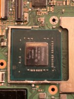

Yeah, can’t see much in those pics. Make sure there isn’t bridging or any resistors or lifted on one side. Sp1 resistor and the one next to it looks a little iffy but can’t tell for sure. As @Nagaa stated one of them could be toast as well.Sorry, that’s all my cellphone can make zoom and focus
I read that resistor had 4.7k valor, you know if in the normal switch motherboard it’s a resistor with that value?If you get purple screen when booting without the chip, the resistor on cmd point is probably dead
Not sure of the value but you may also want to check the A point. SP1 and SP2 are actually capacitors and not resistors so you would have to remove from circuit to get proper uF readings.
Well, I'm not sure regarding the CMD resistor value, but once I saw on youtube that a 4.7kOhm worked, though check on this post to see if there's more info.
Before moving on with a replacement, see if you get any resistance reading of the CMD point, and ensure that the other components are OK as suggested before:
Before moving on with a replacement, see if you get any resistance reading of the CMD point, and ensure that the other components are OK as suggested before:
- use a multimeter and perform reading in diode mode (black probe on GND) for the SP1 and SP2 caps, starting from the left side, you should be getting values inside this range:
- SP1 --> 0 17.9 Ohm
- SP2 --> 18.3 Ohm 0
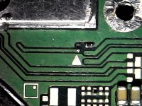
- ensure that there's no short between the CLK point and GND, since in the picture it seems that the ground solder mask nearby the CLK point was removed.
- remove the DAT0 adapter if you did not reflow it.
- Clean everything with IPA.
Nothing wrong in the APU, all resistors are in his place, I think it’s the CMD resistor but idk why the resistor just died, I didn’t nothing wrong, actually I have some experience on micro soldering maybe the chip come faulty or something. Sadly I don't have a donor board or a replacement I need find one on the switch lite or normal switch board to make sure if it’s the problem.Yeah, can’t see much in those pics. Make sure there isn’t bridging or any resistors or lifted on one side. Sp1 resistor and the one next to it looks a little iffy but can’t tell for sure. As @Nagaa stated one of them could be toast as well.
If i remember correctly i can't find the picture anymore but the 3rd resistor on top of the BQ chip on a normal switch can be usedI read that resistor had 4.7k valor, you know if in the normal switch motherboard it’s a resistor with that value?
From experience SP1 and SP2 doesn't cause purple screen, the switch will still work fine without themNot sure of the value but you may also want to check the A point. SP1 and SP2 are actually capacitors and not resistors so you would have to remove from circuit to get proper uF readings.
Last edited by Nagaa,
CMD/A point should be somewhere between .550 and .830 in diode mode.
@Nagaa you are correct does not cause purple screen! It’s been a min since I’ve done any switch repairs. My bad!!
@Nagaa you are correct does not cause purple screen! It’s been a min since I’ve done any switch repairs. My bad!!
Post automatically merged:
Though the same thread says it 4.7k ohm!?!That resistor is 3.5Kohm. I knocked it off myself and lost it. sthetix got the value for me from his working board.
Last edited by kylum,
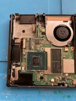
Here are some pictures of the APU and CMD cap, everything looks fine.Not sure of the value but you may also want to check the A point. SP1 and SP2 are actually capacitors and not resistors so you would have to remove from circuit to get proper uF readings.
Attachments
It shouldn’t have anything to do with the APU. My apologies for that as I was got a little confused for a min. You check resistance of the cmd point? Also in diode mode? It could be dead?!?Here are some pictures of the APU and CMD cap, everything looks fine.
What side of the cmd resistor did you solder the wire to? The pic shows extra solder on the opposite side. Not sure if it’s just the photo so I gotta ask!
Last edited by kylum,
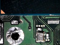
I check th valor of the CMD resistor and gives me 4.66 in diode mode 20k.It shouldn’t have anything to do with the APU. My apologies for that as I was got a little confused for a min. You check resistance of the cmd point? Also in diode mode? It could be dead?!?
What side of the cmd resistor did you solder the wire to? The pic shows extra solder on the opposite side. Not sure if it’s just the photo so I gotta ask!
View attachment 348938
And I soldered in the bottom side of the ressitor I don’t know how that solder got on that place maybe when I remove everything
Post automatically merged:
Well, the switch just turn on randomly, idk why, that happen after make the diagnostic of the resistance, weirdI check th valor of the CMD resistor and gives me 4.66 in diode mode 20k.
And I soldered in the bottom side of the ressitor I don’t know how that solder got on that place maybe when I remove everything
Last edited by Ganesha0112,
replace it, if you have a normal switch motherboard u can take it from itI check th valor of the CMD resistor and gives me 4.66 in diode mode 20k.
And I soldered in the bottom side of the ressitor I don’t know how that solder got on that place maybe when I remove everything
Post automatically merged:
Well, the switch just turn on randomly, idk why, that happen after make the diagnostic of the resistance, weird
You can use a different resistance package, like 0402 or even bigger, and connecting it with wire. The important thing is to use the same resistance value.
Hmm! Yeah I would probably replace it then as already suggested! Verified it’s soldered properly at a minimum. Either way I’m glad it’s turning on now.
FYI, when testing in diode mode the multimeter would not show a “k” value. It’s testing a voltage drop to ground so it should show voltage. Around .550 V to .800 V. You must have been in resistance mode still. Also you test with red prob on ground
FYI, when testing in diode mode the multimeter would not show a “k” value. It’s testing a voltage drop to ground so it should show voltage. Around .550 V to .800 V. You must have been in resistance mode still. Also you test with red prob on ground
Similar threads
- Replies
- 4
- Views
- 3K
- Replies
- 1
- Views
- 599
- Replies
- 0
- Views
- 469
Site & Scene News
New Hot Discussed
-
-
25K views
Wii U and 3DS online services shutting down today, but Pretendo is here to save the day
Today, April 8th, 2024, at 4PM PT, marks the day in which Nintendo permanently ends support for both the 3DS and the Wii U online services, which include co-op play...by ShadowOne333 179 -
22K views
Nintendo Switch firmware update 18.0.1 has been released
A new Nintendo Switch firmware update is here. System software version 18.0.1 has been released. This update offers the typical stability features as all other... -
18K views
The first retro emulator hits Apple's App Store, but you should probably avoid it
With Apple having recently updated their guidelines for the App Store, iOS users have been left to speculate on specific wording and whether retro emulators as we... -
18K views
Delta emulator now available on the App Store for iOS
The time has finally come, and after many, many years (if not decades) of Apple users having to side load emulator apps into their iOS devices through unofficial...by ShadowOne333 96 -
16K views
TheFloW releases new PPPwn kernel exploit for PS4, works on firmware 11.00
TheFlow has done it again--a new kernel exploit has been released for PlayStation 4 consoles. This latest exploit is called PPPwn, and works on PlayStation 4 systems... -
14K views
Nintendo takes down Gmod content from Steam's Workshop
Nintendo might just as well be a law firm more than a videogame company at this point in time, since they have yet again issued their now almost trademarked usual...by ShadowOne333 113 -
13K views
A prototype of the original "The Legend of Zelda" for NES has been found and preserved
Another video game prototype has been found and preserved, and this time, it's none other than the game that spawned an entire franchise beloved by many, the very...by ShadowOne333 31 -
11K views
Anbernic reveals specs details of pocket-sized RG28XX retro handheld
Anbernic is back with yet another retro handheld device. The upcoming RG28XX is another console sporting the quad-core H700 chip of the company's recent RG35XX 2024... -
10K views
Nintendo Switch Online adds two more Nintendo 64 titles to its classic library
Two classic titles join the Nintendo Switch Online Expansion Pack game lineup. Available starting April 24th will be the motorcycle racing game Extreme G and another... -
10K views
Nintendo "Indie World" stream announced for April 17th, 2024
Nintendo has recently announced through their social media accounts that a new Indie World stream will be airing tomorrow, scheduled for April 17th, 2024 at 7 a.m. PT...by ShadowOne333 53
-
-
-
179 replies
Wii U and 3DS online services shutting down today, but Pretendo is here to save the day
Today, April 8th, 2024, at 4PM PT, marks the day in which Nintendo permanently ends support for both the 3DS and the Wii U online services, which include co-op play...by ShadowOne333 -
113 replies
Nintendo officially confirms Switch successor console, announces Nintendo Direct for next month
While rumors had been floating about rampantly as to the future plans of Nintendo, the President of the company, Shuntaro Furukawa, made a brief statement confirming...by Chary -
113 replies
Nintendo takes down Gmod content from Steam's Workshop
Nintendo might just as well be a law firm more than a videogame company at this point in time, since they have yet again issued their now almost trademarked usual...by ShadowOne333 -
97 replies
The first retro emulator hits Apple's App Store, but you should probably avoid it
With Apple having recently updated their guidelines for the App Store, iOS users have been left to speculate on specific wording and whether retro emulators as we...by Scarlet -
96 replies
Delta emulator now available on the App Store for iOS
The time has finally come, and after many, many years (if not decades) of Apple users having to side load emulator apps into their iOS devices through unofficial...by ShadowOne333 -
81 replies
Nintendo Switch firmware update 18.0.1 has been released
A new Nintendo Switch firmware update is here. System software version 18.0.1 has been released. This update offers the typical stability features as all other...by Chary -
80 replies
TheFloW releases new PPPwn kernel exploit for PS4, works on firmware 11.00
TheFlow has done it again--a new kernel exploit has been released for PlayStation 4 consoles. This latest exploit is called PPPwn, and works on PlayStation 4 systems...by Chary -
67 replies
DOOM has been ported to the retro game console in Persona 5 Royal
DOOM is well-known for being ported to basically every device with some kind of input, and that list now includes the old retro game console in Persona 5 Royal...by relauby -
55 replies
Nintendo Switch Online adds two more Nintendo 64 titles to its classic library
Two classic titles join the Nintendo Switch Online Expansion Pack game lineup. Available starting April 24th will be the motorcycle racing game Extreme G and another...by Chary -
53 replies
Nintendo "Indie World" stream announced for April 17th, 2024
Nintendo has recently announced through their social media accounts that a new Indie World stream will be airing tomorrow, scheduled for April 17th, 2024 at 7 a.m. PT...by ShadowOne333
-
Popular threads in this forum
General chit-chat
-
 K3Nv2
Loading…
K3Nv2
Loading… -
 Xdqwerty
Loading…what are you looking at?
Xdqwerty
Loading…what are you looking at? -
 AncientBoi
Loading…
AncientBoi
Loading…
-
-
-
-
-
-
-
-
-
-
-
-
-
-
-
-
-
-
-
-
-
-
-
-
-
@
K3Nv2:
https://www.phonearena.com/phones/compare/Samsung-Galaxy-S22+,Google-Pixel-8a/phones/11762,12219 sad still basically on pair

