


Correct, colors dont matter anymore, now the codes are in pulses (like morse)Thank you I bridged the user mode point but it is still flashing green. But I assume since I am using 2.73 it is not required?
You are using an out of date browser. It may not display this or other websites correctly.
You should upgrade or use an alternative browser.
You should upgrade or use an alternative browser.
Staff Posts
Recent threadmarks
sharing files
Important Posts
Recent threadmarks
Firmwaresmotherboard have problem, i buyyou are using sysmmc or emummc ? also what switch firmware is based on 16.0.3 or 16.1.0 ?
Post automatically merged:
i believe you can find some picture somewhere in this thread, its either traces are cut or via are destroyed.
I bought the board on Aliexpress, it crashes a lot without Picofly and the error 2001-0114 and 2001-3539 appears a lotyou are using sysmmc or emummc ? also what switch firmware is based on 16.0.3 or 16.1.0 ?
Post automatically merged:
i believe you can find some picture somewhere in this thread, its either traces are cut or via are destroyed.

Today I got a problem that my friend's switch could not power on. After measuring I realized that it had a short on 3.3v and ground, a caps on picofly died. Remove the picofly and switch boot again. Anyone know which caused that caps shorted? 

Post some pics of your install. Out of the top of my head I would say the pico touched the metal shield and shorted somewhere, but without pics that's hard to confirm. Maybe the solder you aplied poked through the capton tape or whatever you used for insulation, but this is just speculation.Today I got a problem that my friend's switch could not power on. After measuring I realized that it had a short on 3.3v and ground, a caps on picofly died. Remove the picofly and switch boot again. Anyone know which caused that caps shorted?
Not caps. Usually 3.3v regulator dies when working with external power, that is why it is recommended to remove itToday I got a problem that my friend's switch could not power on. After measuring I realized that it had a short on 3.3v and ground, a caps on picofly died. Remove the picofly and switch boot again. Anyone know which caused that caps shorted?
Post automatically merged:
ok, removed the SRAM powerdown, pls try itI kind of fixed that part, and the slow emmc problem disappeared.
Last edited by rehius,


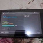
Hi @abal1000x , just to inform that i have 2 oled unit that throw dat0 error when using 100ohm.. i replace it with 47ohm and its boots. So this resistor value is still not universal for all cases.
Will try 2.75 to see if slow issue and sleep battery drain is better.
Will try 2.75 to see if slow issue and sleep battery drain is better.
Post automatically merged:
Firmware is good, tested, safe to upgrade i think.Hi @abal1000x , just to inform that i have 2 oled unit that throw dat0 error when using 100ohm.. i replace it with 47ohm and its boots. So this resistor value is still not universal for all cases.
Will try 2.75 to see if slow issue and sleep battery drain is better.
Last edited by cgtchy0412,
- Joined
- Jul 12, 2010
- Messages
- 162
- Trophies
- 1
- Age
- 36
- Location
- Bananna Land.
- Website
- www.nerdfy.com.br
- XP
- 844
- Country

@abal1000x, I did my second installation using the alternative method of the mosphet on the back of the board on a switch lite (2002), but I am experiencing very long boot times. Basically like this:
- blinks blue 2 to 8 seconds then white ==> boots hekate.
- sometime blinks blue 10 to 25 seconds then white ==> black screen or boots OFW.
- if there is a black screen, and press power again: it boots hekate.
In this case, would it be more appropriate to redo the installation on the CPU capacitors directly? using two mosfets? Can I just cut the MOSFET cable on the back of the board to make it unusable, without having to desolder the rear capacitor cables?
Are you using the new rp2040 tiny? it happened to two of FXDX's installs. he added additional 47ohm on dat0 and they would not boot, but booted fine when he removed them.Hi @abal1000x , just to inform that i have 2 oled unit that throw dat0 error when using 100ohm.. i replace it with 47ohm and its boots. So this resistor value is still not universal for all cases.
Will try 2.75 to see if slow issue and sleep battery drain is better.
Post automatically merged:
Firmware is good, tested, safe to upgrade i think.

Seems like CMD/DAT0/CLK issue.@abal1000x, I did my second installation using the alternative method of the mosphet on the back of the board on a switch lite (2002), but I am experiencing very long boot times. Basically like this:
- blinks blue 2 to 8 seconds then white ==> boots hekate.
- sometime blinks blue 10 to 25 seconds then white ==> black screen or boots OFW.
- if there is a black screen, and press power again: it boots hekate.
In this case, would it be more appropriate to redo the installation on the CPU capacitors directly? using two mosfets? Can I just cut the MOSFET cable on the back of the board to make it unusable, without having to desolder the rear capacitor cables?
If you decide to redo without removing the mosfet, cut the gate line is enough, but to be safe add resistor (pulldown) on the gate to gnd, to make sure there are no charge accumulated in there.
Post automatically merged:
Did the update solve that problem?Hi @abal1000x , just to inform that i have 2 oled unit that throw dat0 error when using 100ohm.. i replace it with 47ohm and its boots. So this resistor value is still not universal for all cases.
Will try 2.75 to see if slow issue and sleep battery drain is better.
Post automatically merged:
Firmware is good, tested, safe to upgrade i think.
I always remove 3.3v regulator when installing picofly. The short on rp2040 board is gone after I removed the bad caps.
Post automatically merged:
Not caps. Usually 3.3v regulator dies when working with external power, that is why it is recommended to remove it
Post automatically merged:
Not sure yet. But both unit are now using 47.. with new firmware they dont raise slow emmc warning at least.Did the update solve that problem?
Just as what i am suspecting. Hopefully this will fixed any 'slow emmc' stuff. Logically it should, except if some other unknown scenario happenedNot sure yet. But both unit are now using 47.. with new firmware they dont raise slow emmc warning at least.

No .. im using green Pi Pico. Maybe with 100ohm dat0 the voltage is on the low side of firmware check so it throws error, as maybe if there is no check inplace it woild boot.. just maybe.Are you using the new rp2040 tiny? it happened to two of FXDX's installs. he added additional 47ohm on dat0 and they would not boot, but booted fine when he removed them.
Post automatically merged:
At least now its safe to know that pico will go to lowest power mode after glitch.Just as what i am suspecting. Hopefully this will fixed any 'slow emmc' stuff. Logically it should, except if some other unknown scenario happened
Post automatically merged:
Let us now whether that will improve glicth time or not, as I suspect it wouldnt.@abal1000x, I did my second installation using the alternative method of the mosphet on the back of the board on a switch lite (2002), but I am experiencing very long boot times. Basically like this:
- blinks blue 2 to 8 seconds then white ==> boots hekate.
- sometime blinks blue 10 to 25 seconds then white ==> black screen or boots OFW.
- if there is a black screen, and press power again: it boots hekate.
In this case, would it be more appropriate to redo the installation on the CPU capacitors directly? using two mosfets? Can I just cut the MOSFET cable on the back of the board to make it unusable, without having to desolder the rear capacitor cables?
Last edited by cgtchy0412,

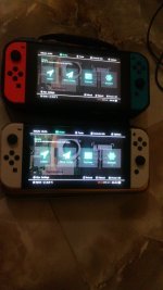


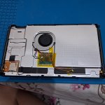
Apparently you're going to need a transparent shell in order to see leds on the switch liteHi everyone, when installing hwfly picofly rp2040 based on switch lite,
we cannot see the led indicator when backplate is putting back since the chip is located at the left of the CPU..
Any idea or solution to be able to see the led indicator on switch lites ?

Hi everyone, when installing hwfly picofly rp2040 based on switch lite,
we cannot see the led indicator when backplate is putting back since the chip is located at the left of the CPU..
Any idea or solution to be able to see the led indicator on switch lites ?
Attachments
- Joined
- Sep 2, 2020
- Messages
- 1,342
- Trophies
- 0
- Age
- 39
- Location
- TORONTO
- Website
- form.jotform.com
- XP
- 2,277
- Country

If on top of emmc area, you still can see through game cartridge slotHi everyone, when installing hwfly picofly rp2040 based on switch lite,
we cannot see the led indicator when backplate is putting back since the chip is located at the left of the CPU..
Any idea or solution to be able to see the led indicator on switch lites ?

A polysh pen
Post automatically merged:
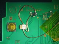
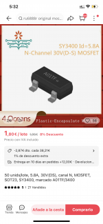
Back side done
which mosfet would be the equivalent of 8342 in a sof23 type package to solder directly to the motherboard
Attachments
Similar threads
- Replies
- 5
- Views
- 2K
- Replies
- 2
- Views
- 838
- Replies
- 42
- Views
- 7K
Site & Scene News
New Hot Discussed
-
-
39K views
New static recompiler tool N64Recomp aims to seamlessly modernize N64 games
As each year passes, retro games become harder and harder to play, as the physical media begins to fall apart and becomes more difficult and expensive to obtain. The... -
18K views
Majora’s Mask PC port 2Ship2Harkinian gets its first release
After several months of work, the Harbour Masters 64 team have released their first public build of 2Ship2Harkinian, a feature-rich Majora's Mask PC port. This comes... -
17K views
Anbernic reveals the RG35XXSP, a GBA SP-inspired retro handheld
Retro handheld manufacturer Anbernic has revealed its first clamshell device: the Anbernic RG35XXSP. As the suffix indicates, this handheld's design is inspired by... -
17K views
Mario Builder 64 is the N64's answer to Super Mario Maker
With the vast success of Super Mario Maker and its Switch sequel Super Mario Maker 2, Nintendo fans have long been calling for "Maker" titles for other iconic genres... -
13K views
The founder of Oculus is releasing a $199 FPGA Game Boy system
Palmer Luckey is known for his pursuits into the world of virtual reality, having founded Oculus and designed the Rift VR headset. Prior to the $2 billion dollar... -
13K views
Ubisoft reveals 'Assassin's Creed Shadows' which is set to launch later this year
Ubisoft has today officially revealed the next installment in the Assassin's Creed franchise: Assassin's Creed Shadows. This entry is set in late Sengoku-era Japan... -
13K views
RetroArch is now available in the Apple Store for iOS devices
Another day, another great emulator that makes its way into the Apple Store for more users to enjoy. With Apple opening its store up to videogame emulators earlier...by ShadowOne333 58 -
12K views
The Kingdom Hearts games are coming to Steam
After a little more than three years of exclusivity with the Epic Games Store, Square Enix has decided to bring their beloved Kingdom Hearts franchise to Steam. The... -
10K views
Nintendo takes down the Breath of the Wild randomizer mod from Gamebanana
Another day, another Nintendo DMCA takedown against fan-made content. Just a few minutes ago, Nintendo issued a DMCA takedown notice against a widely known and...by ShadowOne333 87 -
9K views
PS1 emulator "Gamma" has been added to the Apple Store for iOS devices
Continuing with the number of available retro emulators found in the Apple Store, after Apple's decision to finally allow videogame emulators on their store, another...by ShadowOne333 48
-
-
-
162 replies
The founder of Oculus is releasing a $199 FPGA Game Boy system
Palmer Luckey is known for his pursuits into the world of virtual reality, having founded Oculus and designed the Rift VR headset. Prior to the $2 billion dollar...by Chary -
145 replies
New static recompiler tool N64Recomp aims to seamlessly modernize N64 games
As each year passes, retro games become harder and harder to play, as the physical media begins to fall apart and becomes more difficult and expensive to obtain. The...by Chary -
104 replies
Majora’s Mask PC port 2Ship2Harkinian gets its first release
After several months of work, the Harbour Masters 64 team have released their first public build of 2Ship2Harkinian, a feature-rich Majora's Mask PC port. This comes...by Scarlet -
96 replies
Ubisoft reveals 'Assassin's Creed Shadows' which is set to launch later this year
Ubisoft has today officially revealed the next installment in the Assassin's Creed franchise: Assassin's Creed Shadows. This entry is set in late Sengoku-era Japan...by Prans -
90 replies
The Kingdom Hearts games are coming to Steam
After a little more than three years of exclusivity with the Epic Games Store, Square Enix has decided to bring their beloved Kingdom Hearts franchise to Steam. The...by Chary -
87 replies
Nintendo takes down the Breath of the Wild randomizer mod from Gamebanana
Another day, another Nintendo DMCA takedown against fan-made content. Just a few minutes ago, Nintendo issued a DMCA takedown notice against a widely known and...by ShadowOne333 -
67 replies
Select PlayStation 2 games are coming to PlayStation 5
Sony is once more attempting to reintroduce players to their older library of games by re-releasing classic PlayStation 2 titles onto the PlayStation Store. During...by Chary -
65 replies
Anbernic reveals the RG35XXSP, a GBA SP-inspired retro handheld
Retro handheld manufacturer Anbernic has revealed its first clamshell device: the Anbernic RG35XXSP. As the suffix indicates, this handheld's design is inspired by...by Prans -
65 replies
Mario Builder 64 is the N64's answer to Super Mario Maker
With the vast success of Super Mario Maker and its Switch sequel Super Mario Maker 2, Nintendo fans have long been calling for "Maker" titles for other iconic genres...by Scarlet -
63 replies
PlayStation State of Play May 2024 showcase - God of War: Ragnarok coming to PC
The latest State of Play is here. This is PlayStation's Summer showcase, providing updates to new updates on upcoming games and brand new reveals. The 35-minute...by Chary
-
Popular threads in this forum
General chit-chat
- No one is chatting at the moment.
-
-
-
-
-
-
-
-
-
 @
BigOnYa:
He was the ass of gbatemp, everyone knocked on him, I honestly felt bad, even though I was guilty myself, but he egged it all on himself,
@
BigOnYa:
He was the ass of gbatemp, everyone knocked on him, I honestly felt bad, even though I was guilty myself, but he egged it all on himself, -
-
-
@
BigOnYa:
I feel like gbatemp should make t-shirts or memorabilia to remember the lost ones. I bet the Polly shirts would sell out quick.
-
-
-
-
@
BigOnYa:
Your correct, Somebody would be guilty and there would be riots, then they storm the gbatemp capitol,
-
 @
K3Nv2:
Online or not there are still certain rights that judges would have no issue handing out a warrant over
@
K3Nv2:
Online or not there are still certain rights that judges would have no issue handing out a warrant over -
-
@
BigOnYa:
Honestly I'm scared to, from you, but ok, lemme turn on vpn, virtual machine, private browser first
-
-
-
@
BigOnYa:
That robot is here somewhere, I hear it moving around at night, but I haven't seen it for months.
-
@
BigOnYa:
Oh that laptop I give to ancientboi, so you been watching him for months, and he's been watching you
-
-