Tutorial  Updated

How to flash the HWFLY Clone chips

See below for updates.

IF YOU BREAK YOUR BOOT0 PIN. DO NOT DM ME ASKING FOR HELP. THAT'S IT. YOU BREAK THAT PIN AND YOU CANT FLASH. YOUR CHIP IS STUCK WITH WHATEVER HWFLY PUT ON IT


Pre-requisites:


  • Raspberry Pi Zero W
    • You may use another flasher if you desire.
  • Pinout Diagram
  • Modchip Diagram
  • FULL_CHIP_STOCK.bin
  • Modchip Diagram, find the PA9(TX) and the PA10(RX) pins on your modchip, and do the following:
    • Connect GPIO14(TX) on your Raspberry Pi Zero W to the PA10(RX) pin on your modchip.
    • Connect GPIO15(RX) on your Raspberry Pi Zero W to the PA9(TX) pin on your modchip.

  1. Solder a wire to each of the following pinouts on the Raspberry Pi Zero W:
    • 3.3V
    • Ground
    • GPIO 14 (UART TX)
    • GPIO 15 (UART RX)
  2. Do the following to prepare the modchip:
    1. Lift pin 44 (also known as BOOT0).
    2. You will need a way to power the chip, so you need to find two 3.3v points. It can be on a MOSFET, but it will differ based on the revision of the modchip.
    3. Connect Ground on your Raspberry Pi Zero W to the Ground pin on your modchip.
    4. Check the Modchip Diagram, find the PA9(TX) and the PA10(RX) pins on your modchip, and do the following:
      • Connect GPIO14(TX) on your Raspberry Pi Zero W to the PA10(RX) pin on your modchip.
      • Connect GPIO15(RX) on your Raspberry Pi Zero W to the PA9(TX) pin on your modchip.
  3. Boot your Raspberry Pi Zero W and do the following:
    1. In the terminal, type the following command, and press enter:
      Bash:
      sudo nano /boot/config.txt
    2. Add the following line to the end of the file:
      INI:
      dtoverlay=pi3-miniuart-bt
    3. Press CTRL + X to save and exit the editor.
    4. In the terminal, type the following command, and press enter:
      Bash:
      sudo nano /boot/cmdline.txt
    5. Remove the following line from the file:
      INI:
      console=serial0,115200
    6. Press CTRL + X to save and exit the editor.
    7. Restart your Raspberry Pi with this command
      Bash:
      sudo /sbin/reboot
    8. In the terminal, type the following commands, and press enter after each command:

      Bash:
      git clone https://github.com/Pheeeeenom/stm32flash.git
      cd stm32flash
      sudo make install
  4. Now you will flash the modchip.
    Note: This will remove read protection, and the modchip will wipe itself (that is what we want).
    1. In the terminal, type the following command, and press enter:
      Bash:
      stm32flash -k /dev/serial0
    2. Now to flash Spacecraft-NX Version 0.2.0, type the following, and press enter:
      Bash:
      stm32flash -v -w ./FULL_CHIP_STOCK.bin /dev/serial0
  5. Once you're done flashing your modchip, remove the wiring from the modchip, and restore the 3.3v pin on the modchip to its original position.

Please post pictures of your work here to further the identification of the different board revisions!


UPDATE: So it seems like stitching the spacecraft bootloader and firmware together from the repo causes unstable glitching behaviors. For now, consistent glitching behavior works with this bootload/firmware combo.
This is the original file on the OLED variant chip which has 0.2.0 spacecraft. As for glitching, I'll figure it out, give me some time...unless someone else wants to hop in and reverse the differences.

For now, this at least solves the 0.1.0 HWFLY gen 3 issue. More to come.

UPDATE 2: This is only going to work on some HWFLY chips. Older ones use higher protection than the new revisions that seem to use the QFN FPGA.

UPDATE 3: This should fully work on OLED modchips with the QFN FPGA. https://github.com/Pheeeeenom/firmware
 
Last edited by Mena,

urherenow

Well-Known Member
Member
Joined
Mar 8, 2009
Messages
4,811
Trophies
2
Age
48
Location
Japan
XP
3,718
Country
United States
Ok, I'm tired of waiting, and I have everything I *need* to install the chip, just not everything I *wanted*. Namely, my dat0 break-out adapter hasn't arrived yet.

So what's the worst scenario with using the tiny corner dat0 adapter that comes with the chip? If problems arise later on (after a successful install), is the damage permanent, or semi-permanent with the need to remove the chip entirely and re-ball it? Or can you remove it later and replace it with the other adapter later on, if necessary?

Assuming I get it in place, and after soldering the corner part to hold it steady, I get a good reading with a meter, is it a bad idea to go around the edges with the green UV solder mask stuff to 'glue' it in place even better?
 

doom95

Well-Known Member
Member
Joined
Aug 12, 2019
Messages
303
Trophies
0
Age
24
XP
785
Country
Netherlands
if you bridge dat0/dat1 you could potentially corrupt nand and lose online capability permanently

but you have to really mess up to do so. if you're competent and properly measure your connection it'll be fine
 

urherenow

Well-Known Member
Member
Joined
Mar 8, 2009
Messages
4,811
Trophies
2
Age
48
Location
Japan
XP
3,718
Country
United States
if you bridge dat0/dat1 you could potentially corrupt nand and lose online capability permanently

but you have to really mess up to do so. if you're competent and properly measure your connection it'll be fine
Ok, so I've see 2 install videos that I like, and I've seen the wiring diagrams... but I haven't seen a list of exact values to check the solder points with. In fact, the ModzvilleUSA video checks everything against ground... so how do you test for dat0 getting bridged to dat1?

EDIT: So sthetix's video says to check the adapter for anything between 500~800 between the pad and ground (but consistently reads 617~619 in his video). What would the reading be if d0&d1 were bridged? I know... I'm being paranoid... This sucker WILL be installed tomorrow...
 
Last edited by urherenow,

de9ed

Well-Known Member
Member
Joined
Oct 22, 2020
Messages
278
Trophies
0
Age
30
XP
919
Country
Canada
Ok, so I've see 2 install videos that I like, and I've seen the wiring diagrams... but I haven't seen a list of exact values to check the solder points with. In fact, the ModzvilleUSA video checks everything against ground... so how do you test for dat0 getting bridged to dat1?

EDIT: So sthetix's video says to check the adapter for anything between 500~800 between the pad and ground (but consistently reads 617~619 in his video). What would the reading be if d0&d1 were bridged? I know... I'm being paranoid... This sucker WILL be installed tomorrow...
after installing 30 + oled mods. the corner dat0 works as well as other solder anchor adapters. the dat0 diode value ranges from 400-450 ( usually 425) (red on ground and black on dat0 on a fluke)
 

urherenow

Well-Known Member
Member
Joined
Mar 8, 2009
Messages
4,811
Trophies
2
Age
48
Location
Japan
XP
3,718
Country
United States
after installing 30 + oled mods. the corner dat0 works as well as other solder anchor adapters. the dat0 diode value ranges from 400-450 ( usually 425) (red on ground and black on dat0 on a fluke)
Did not want to hear that... I measured in the low 600s like sthetix. I've been awake all night trying to get this done, and I'm trying to train it now. It's been slow-blinking Yellow for more than 10 minutes now... dunno if it's working. I can say that my really cheap meter couldn't read anything directly from the rst point. I also don't know if I messed up clk either, but it's not reading a short to ground and IS reading... something (I think also in the 600s... can't remember now) :unsure:

UPDATE: Still not working. I can't flash with the firmware dongle either. I get a yellow light, like I'm supposed to. Windows (10) shows it as COM 3. When I double-click flash.bat, it says device not found. Firmware only, I get Spacecraft-nx DFU not found.
 
Last edited by urherenow,

kylum

Well-Known Member
Member
Joined
Dec 8, 2008
Messages
394
Trophies
1
XP
1,484
Country
United States
Did not want to hear that... I measured in the low 600s like sthetix. I've been awake all night trying to get this done, and I'm trying to train it now. It's been slow-blinking Yellow for more than 10 minutes now... dunno if it's working. I can say that my really cheap meter couldn't read anything directly from the rst point. I also don't know if I messed up clk either, but it's not reading a short to ground and IS reading... something (I think also in the 600s... can't remember now) :unsure:

UPDATE: Still not working. I can't flash with the firmware dongle either. I get a yellow light, like I'm supposed to. Windows (10) shows it as COM 3. When I double-click flash.bat, it says device not found. Firmware only, I get Spacecraft-nx DFU not found.
FYI, I can’t get my computer to flash via the dongle no matter what. Every other usb device i throw at it works just fine. I had to use a different computer to flash it with the dongle. Flashing with an ST-link on the pc that won’t flash through the dongle works.

Did you ever flash that chip or is it stock?
 

PamanX

Member
Newcomer
Joined
Jan 12, 2022
Messages
11
Trophies
0
Age
37
XP
108
Country
Mexico
FYI, I can’t get my computer to flash via the dongle no matter what. Every other usb device i throw at it works just fine. I had to use a different computer to flash it with the dongle. Flashing with an ST-link on the pc that won’t flash through the dongle works.

Did you ever flash that chip or is it stock?
I had the same problem when trying to update the firmware of the chip, the flash.bat gave me an error or the window remained black, my solution was to connect the usb cable to the pc and almost at the same time hit enter to open the .bat and so it starts to update, try doing this
 

PamanX

Member
Newcomer
Joined
Jan 12, 2022
Messages
11
Trophies
0
Age
37
XP
108
Country
Mexico
Did not want to hear that... I measured in the low 600s like sthetix. I've been awake all night trying to get this done, and I'm trying to train it now. It's been slow-blinking Yellow for more than 10 minutes now... dunno if it's working. I can say that my really cheap meter couldn't read anything directly from the rst point. I also don't know if I messed up clk either, but it's not reading a short to ground and IS reading... something (I think also in the 600s... can't remember now) :unsure:

UPDATE: Still not working. I can't flash with the firmware dongle either. I get a yellow light, like I'm supposed to. Windows (10) shows it as COM 3. When I double-click flash.bat, it says device not found. Firmware only, I get Spacecraft-nx DFU not found.

FYI, I can’t get my computer to flash via the dongle no matter what. Every other usb device i throw at it works just fine. I had to use a different computer to flash it with the dongle. Flashing with an ST-link on the pc that won’t flash through the dongle works.

Did you ever flash that chip or is it stock?

I had the same problem when trying to update the firmware of the chip, the flash.bat gave me an error or the window remained black, my solution was to connect the usb cable to the pc and almost at the same time hit enter to open the .bat and so it starts to update, try doing this
 

kylum

Well-Known Member
Member
Joined
Dec 8, 2008
Messages
394
Trophies
1
XP
1,484
Country
United States
I had the same problem when trying to update the firmware of the chip, the flash.bat gave me an error or the window remained black, my solution was to connect the usb cable to the pc and almost at the same time hit enter to open the .bat and so it starts to update, try doing this
No need to try as my laptop works for flashing just not my main PC. Plus I already flashed it and the new Hwfly toolbox works great as well. I know it’s just a driver issue causing the problem. I’ll fix it by reinstalling windows but I’m just not ready to do that yet.
 

doom95

Well-Known Member
Member
Joined
Aug 12, 2019
Messages
303
Trophies
0
Age
24
XP
785
Country
Netherlands

Attachments

  • unknown.png
    unknown.png
    61.9 KB · Views: 106

de9ed

Well-Known Member
Member
Joined
Oct 22, 2020
Messages
278
Trophies
0
Age
30
XP
919
Country
Canada
Did not want to hear that... I measured in the low 600s like sthetix. I've been awake all night trying to get this done, and I'm trying to train it now. It's been slow-blinking Yellow for more than 10 minutes now... dunno if it's working. I can say that my really cheap meter couldn't read anything directly from the rst point. I also don't know if I messed up clk either, but it's not reading a short to ground and IS reading... something (I think also in the 600s... can't remember now) :unsure:

UPDATE: Still not working. I can't flash with the firmware dongle either. I get a yellow light, like I'm supposed to. Windows (10) shows it as COM 3. When I double-click flash.bat, it says device not found. Firmware only, I get Spacecraft-nx DFU not found.
pm me or add me on discord. i'll try to help you there. did you do red on ground and black on Dat0 or RST ?
 

urherenow

Well-Known Member
Member
Joined
Mar 8, 2009
Messages
4,811
Trophies
2
Age
48
Location
Japan
XP
3,718
Country
United States
pm me or add me on discord. i'll try to help you there. did you do red on ground and black on Dat0 or RST ?
PMed you... I don't know your discord user name... which channel?

EDIT: So... I have a work laptop with me, and I was able to flash with that. But then, I was told on discord that the 0.6.0 is supposed to be flashed AFTER you've already trained. I changed out my dat0 adaper and now get like .412 with red on ground, and .635 with black on ground. I immediately get a solid purple light.

Now that I've flashed 0.6.0, I do not get an amber light with the USB dongle attached... it flashes... blue, I think. Tried to flash r023 back with my bootloader backup, and it didn't seem to flash correctly, but it went back to a steady blinking yellow when powering it on. Tried flashing to 0.5.0 from there... seems like the bootloader flashes but not the firmware.

But... with 0.5.0 or 0.6.0 *attempted* flashes, it goes back to a purple light, but at least HOS boots. So my system is not bricked. I just have a purple light shining out of it unless I completely shut it off.

I should have waited for better flux and a better microscope to arrive, and I should have looked for one of those small J tips. No hacked OLED for me this weekend :sad:

Or... maybe ever. With the rest of the things I think I need, I don't think I want to mess with that via point at all. Only thing I would think to do, is swap out the cpu adapter, but I can't imagine I've messed that up without bricking...

Is there an installer in Japan?
 
Last edited by urherenow,

fragged

Well-Known Member
Member
Joined
Jun 19, 2018
Messages
229
Trophies
0
Age
39
XP
1,259
Country
United States
PMed you... I don't know your discord user name... which channel?

EDIT: So... I have a work laptop with me, and I was able to flash with that. But then, I was told on discord that the 0.6.0 is supposed to be flashed AFTER you've already trained. I changed out my dat0 adaper and now get like .412 with red on ground, and .635 with black on ground. I immediately get a solid purple light.

Now that I've flashed 0.6.0, I do not get an amber light with the USB dongle attached... it flashes... blue, I think. Tried to flash r023 back with my bootloader backup, and it didn't seem to flash correctly, but it went back to a steady blinking yellow when powering it on. Tried flashing to 0.5.0 from there... seems like thbee bootloader flashes but not the firmware.

But... with 0.5.0 or 0.6.0 *attempted* flashes, it goes back to a purple light, but at least HOS boots. So my system is not bricked. I just have a purple light shining out of it unless I completely shut it off.

I should have waited for better flux and a better microscope to arrive, and I should have looked for one of those small J tips. No hacked OLED for me this weekend :sad:

Or... maybe ever. With the rest of the things I think I need, I don't think I want to mess with that via point at all. Only thing I would think to do, is swap out the cpu adapter, but I can't imagine I've messed that up without bricking...

Is there an installer in Japan?
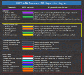
Where did you hear that you're supposed to have the chip train before flashing the new 0.6.0 release? That's not been my experience, just flash both bootloader (which is needed for the new LED status indicators) & firmware. Connect over USB serial with putty to whichever COM port it is listed under Device Manager, USB Devices. In Putty type V for version to make sure the chip is connected. Then E to erase the payload on boot0, followed by P to program the new payload to boot0, finally T to train the chip which is much faster with this new release.
Hopefully the new LED indicators can help you to tell where to look to fix your issue.
 

Attachments

  • glitch.gif
    glitch.gif
    780.2 KB · Views: 98
  • Like
Reactions: Donnie-Burger

Vladjaye

Well-Known Member
Newcomer
Joined
Jan 11, 2021
Messages
48
Trophies
0
Age
28
XP
379
Country
United States
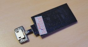
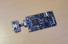
Just a quick question - can I flash the Oled chip with the 0.5 firmware using micro-usb instead of toolbox? Is the process the same as usual if yes? Run .bat and that's it? Got one for friend recently, but it came in a bit different condition - the chip has V marking and the sticker on back side. Also, the micro-usb cable was already connected out of the box. I suspect it was flashed with something new in China. Just want to get 0.5 versio basically, before installing the chip.
 

Attachments

  • 8051380a-d741-4c50-9c20-c609a100ca97.jpg
    8051380a-d741-4c50-9c20-c609a100ca97.jpg
    858.5 KB · Views: 84
  • 918b31d2-c4e1-4556-9f07-9fa1bbab91d4.jpg
    918b31d2-c4e1-4556-9f07-9fa1bbab91d4.jpg
    1 MB · Views: 103

fragged

Well-Known Member
Member
Joined
Jun 19, 2018
Messages
229
Trophies
0
Age
39
XP
1,259
Country
United States
Just a quick question - can I flash the Oled chip with the 0.5 firmware using micro-usb instead of toolbox? Is the process the same as usual if yes? Run .bat and that's it? Got one for friend recently, but it came in a bit different condition - the chip has V marking and the sticker on back side. Also, the micro-usb cable was already connected out of the box. I suspect it was flashed with something new in China. Just want to get 0.5 versio basically, before installing the chip.
You should flash the newest 0.6.0 version, you may have to grab the .bat file from the previous release as you want to flash both the bootloader & firmware. That way you get the new indicator LEDs which should help troubleshoot your installation if anything isn't quite right:
https://github.com/hwfly-nx/firmware/releases
 
  • Like
Reactions: Donnie-Burger

Dean_

Well-Known Member
Member
Joined
Sep 11, 2014
Messages
684
Trophies
0
XP
712
Country
I tried updating 0.6.0-beta1 to 0.6.0-beta2 using included hwfly-toolbox.
It refused updating because of the same version number, so I put .force_update file in the sdcard and updated firmware.
But somehow update went wrong and after rebooting no light was coming from the modchip.
The firmware was broken and it always booted straight to OFW with no light.
I flashed 0.6.0-beta2 using ST-LINK and now it's working better than ever.
I think some additional safety measure can be useful.
 

fragged

Well-Known Member
Member
Joined
Jun 19, 2018
Messages
229
Trophies
0
Age
39
XP
1,259
Country
United States
I tried updating 0.6.0-beta1 to 0.6.0-beta2 using included hwfly-toolbox.
It refused updating because of the same version number, so I put .force_update file in the sdcard and updated firmware.
But somehow update went wrong and after rebooting no light was coming from the modchip.
The firmware was broken and it always booted straight to OFW with no light.
I flashed 0.6.0-beta2 using ST-LINK and now it's working better than ever.
I think some additional safety measure can be useful.
I had a similar issue with the first version of 0.6.0 when flashed on the Switch itself. It went into training mode, showed glitching with the LED & even got a blue light signaling it was complete. However after trying to boot I was only getting a pulsing green LED & it would not boot at all.
It worked fine after flashing my SX Lite with Putty over USB serial.
At this point I would not recommend that anyone without the ability to externally flash their chip manually wait for more testing before trying to flash these newest versions through hwfly-toolbox.
If I didn't have the USB flex for the chip & the tools to open my OLED it would be essentially a brick right now.
 

urherenow

Well-Known Member
Member
Joined
Mar 8, 2009
Messages
4,811
Trophies
2
Age
48
Location
Japan
XP
3,718
Country
United States
Where did you hear that you're supposed to have the chip train before flashing the new 0.6.0 release? That's not been my experience, just flash both bootloader (which is needed for the new LED status indicators) & firmware. Connect over USB serial with putty to whichever COM port it is listed under Device Manager, USB Devices. In Putty type V for version to make sure the chip is connected. Then E to erase the payload on boot0, followed by P to program the new payload to boot0, finally T to train the chip which is much faster with this new release.
Hopefully the new LED indicators can help you to tell where to look to fix your issue.
The person I said I PMed on discord. What speed should be used with putty? I set it for serial on COM3 with default speed of 9600, and I get a blank screen with a green square (Curser?) on the top-left. I press v and the LED turns white. If I try the flash-bootloader.bat, I get the dots on the screen, the LED turns white, and it says it timed out waiting for the updater to boot. The flash-firmware.bat seems to work, however...
 

algolsaturn

Member
Newcomer
Joined
Feb 15, 2022
Messages
8
Trophies
0
Location
Earth
XP
116
Country
Australia
Where did you hear that you're supposed to have the chip train before flashing the new 0.6.0 release? That's not been my experience, just flash both bootloader (which is needed for the new LED status indicators) & firmware. Connect over USB serial with putty to whichever COM port it is listed under Device Manager, USB Devices. In Putty type V for version to make sure the chip is connected. Then E to erase the payload on boot0, followed by P to program the new payload to boot0, finally T to train the chip which is much faster with this new release.
Hopefully the new LED indicators can help you to tell where to look to fix your issue.
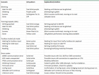
Are those led colour codes indifferent to what version of the firmware you are on. Say if you have one of those OLED modchips that are unable to be flashed and have the stock 0.2 firmware, can that still be used as a reference?

EDIT: if not, is there any sort of reference sheet with the different colours and their meanings for the older firmware versions. Thanks.
 

Site & Scene News

Popular threads in this forum

General chit-chat
Help Users
    Psionic Roshambo @ Psionic Roshambo: Please click all suspicious links sent your email