


I apologize for my poor English. Perhaps I didn't express it clearly, and maybe I shouldn't have used the term "freeze." The issue is that sometimes when I click on the power-off or restart option, the Switch screen goes black directly. When I try to turn it on by pressing the power button again, it doesn't respond, and the LED on the RP2040 chip remains off. I have to perform a 10-second long press of the power button to have a chance of turning it on. Sometimes it can restart normally, but the probability of a failed restart is between 70% and 90%.oh sorry - i missed the freezing part. it didnt freeze for me tbh - it just sometimes doesnt flash on first try for me (without a freeze) sorry for the confusion
You are using an out of date browser. It may not display this or other websites correctly.
You should upgrade or use an alternative browser.
You should upgrade or use an alternative browser.
Staff Posts
Recent threadmarks
sharing files
Important Posts
Recent threadmarks
Firmwares
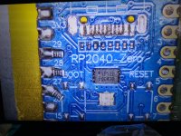
so i manage to remove the button
by manualy soldering
can someone explain to me how the button work ??
when press the button , which number connect ??
you can see from the image i attach ( 1 2 3 4)
if someday i change to 2 pin leg button (the default rp2040 has 4 pin leg)
is it gonna work ???

2 leg pin

if someday i use this 2 leg pin, which number i need to solder ? ( 1 2 3 4 )
by manualy soldering
can someone explain to me how the button work ??
when press the button , which number connect ??
you can see from the image i attach ( 1 2 3 4)
if someday i change to 2 pin leg button (the default rp2040 has 4 pin leg)
is it gonna work ???
2 leg pin
if someday i use this 2 leg pin, which number i need to solder ? ( 1 2 3 4 )

so i manage to remove the button
by manualy soldering
can someone explain to me how the button work ??
when press the button , which number connect ??
you can see from the image i attach ( 1 2 3 4)
if someday i change to 2 pin leg button (the default rp2040 has 4 pin leg)
is it gonna work ???
View attachment 373341
2 leg pin
View attachment 373343
if someday i use this 2 leg pin, which number i need to solder ? ( 1 2 3 4 )
By my experience 3+4 with twezzers
Enviado desde mi iPhone utilizando Tapatalk

Can confirm this. Usually 3 times did the charmthats "normal"
i usually patch the firmware 3-5 times before i reboot and recheck. It usually works for me that way.

Hello everyone, try to install the firmware fw_2.73.uf2 On my rp 2040 Zero, But it didn't give me the red light, the result was a quick green light with a faint red And when reconnecting to verify it gave a blue light and then a series of blinks with the same green light with a faint red.
I made the bridge indicated in the guide and still the result did not change.
Then I tried to flash an older firmware and the result was different With versions from 2.65 and below, now It gave an intense green light, without red this time and when reconnecting to verify, the result It was a blue light and then a slight blue light or turquoise light, for a second.
Do you know what could be a solution?

Use the latest firmware (2.73) and ignore the color code. The error code will be in pulse (not in color anymore) like morse code.Hello everyone, try to install the firmware fw_2.73.uf2 On my rp 2040 Zero, But it didn't give me the red light, the result was a quick green light with a faint red And when reconnecting to verify it gave a blue light and then a series of blinks with the same green light with a faint red.
I made the bridge indicated in the guide and still the result did not change.
Then I tried to flash an older firmware and the result was different With versions from 2.65 and below, now It gave an intense green light, without red this time and when reconnecting to verify, the result It was a blue light and then a slight blue light or turquoise light, for a second.
Do you know what could be a solution?
- Joined
- Sep 2, 2020
- Messages
- 1,283
- Trophies
- 0
- Age
- 39
- Location
- TORONTO
- Website
- form.jotform.com
- XP
- 2,214
- Country

1&3 and 2&4 are bridge together(continuity), also 1&3 are ground, so you can do you combination 1+2 or 3+4 or either 2 or 4 to anywhere ground.so i manage to remove the button
by manualy soldering
can someone explain to me how the button work ??
when press the button , which number connect ??
you can see from the image i attach ( 1 2 3 4)
if someday i change to 2 pin leg button (the default rp2040 has 4 pin leg)
is it gonna work ???
View attachment 373341
2 leg pin
View attachment 373343
if someday i use this 2 leg pin, which number i need to solder ? ( 1 2 3 4 )

I’ve experienced exactly this as well and mentioned that here before. Could be a mofset or the chip. It’s annoying sometimes but a usual person sometimes won’t restart their switch for months.I apologize for my poor English. Perhaps I didn't express it clearly, and maybe I shouldn't have used the term "freeze." The issue is that sometimes when I click on the power-off or restart option, the Switch screen goes black directly. When I try to turn it on by pressing the power button again, it doesn't respond, and the LED on the RP2040 chip remains off. I have to perform a 10-second long press of the power button to have a chance of turning it on. Sometimes it can restart normally, but the probability of a failed restart is between 70% and 90%.
what stencil are you using?trust me its really not that hard . just take ur time .
when u take the emmc take ur time dont try to pull it to early and everything will be fine
also reballing is the easiest part :-)

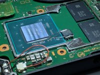
Switch v1 RP2040 w/ 51 ohm resistor &
Single Mosfet w/ 3.3k resistor work and fast boot
Single Mosfet w/ 3.3k resistor work and fast boot
Attachments


Last edited by darviral,

what mosfet did you use?Switch v1 RP2040 w/ 50 ohm resistor &
Single Mosfet w/ 3.3k resistor work and fast boot

1=3 on/off 2=4so i manage to remove the button
by manualy soldering
can someone explain to me how the button work ??
when press the button , which number connect ??
you can see from the image i attach ( 1 2 3 4)
if someday i change to 2 pin leg button (the default rp2040 has 4 pin leg)
is it gonna work ???
View attachment 373341
2 leg pin
View attachment 373343
if someday i use this 2 leg pin, which number i need to solder ? ( 1 2 3 4 )
what mosfet is this?Switch v1 RP2040 w/ 51 ohm resistor &
Single Mosfet w/ 3.3k resistor work and fast boot

what mosfet is this?
I think it's IRF8736

hello ,Use the latest firmware (2.73) and ignore the color code. The error code will be in pulse (not in color anymore) like morse code.
so what is the right code?
I flashed the file , got green light.
Reconnect to pc get blue , than 2 blinks yellow
is that good?

ClickMewhat stencil are you using?
this is what i use
i use 3 layer double sided tap to get it on the hight of 4 neodym magnets i put around the emmc so its flush
then add solder paste
after that u take some tweezers and push in the stencil in the middle down so it doesnt buldge when u heat it up and then u add heat till u see all balls formed
after that i ad a bit more flux
then heat it up again till i see the balls melt again
then i let it cool down a bit take the tweezer of
take the stencil off
add a bit more flux reheat it to make sure the balls are perfect
clean all the flux of
set my dat0 point with solder repair pads
then reflow the emmc and be done with it
all that work takes me 10-15 min
Post automatically merged:
yes thats normalhello ,
so what is the right code?
I flashed the file , got green light.
Reconnect to pc get blue , than 2 blinks yellow
is that good?
What do you guys use for neatly cutting the outer shield so the pico doesn't bulge. I have a mini drill set and I've tried both red bits, which were awful. A simple scissors cuts fine but don't look pretty at the end. Any suggestions among these?
Attachments
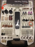
Scissors cleanest cut.What do you guys use for neatly cutting the outer shield so the pico doesn't bulge. I have a mini drill set and I've tried both red bits, which were awful. A simple scissors cuts fine but don't look pretty at the end. Any suggestions among these?
Similar threads
- Replies
- 3
- Views
- 1K
- Replies
- 2
- Views
- 360
- Replies
- 42
- Views
- 6K
Site & Scene News
New Hot Discussed
-
-
24K views
Wii U and 3DS online services shutting down today, but Pretendo is here to save the day
Today, April 8th, 2024, at 4PM PT, marks the day in which Nintendo permanently ends support for both the 3DS and the Wii U online services, which include co-op play...by ShadowOne333 179 -
19K views
Nintendo Switch firmware update 18.0.1 has been released
A new Nintendo Switch firmware update is here. System software version 18.0.1 has been released. This update offers the typical stability features as all other... -
17K views
The first retro emulator hits Apple's App Store, but you should probably avoid it
With Apple having recently updated their guidelines for the App Store, iOS users have been left to speculate on specific wording and whether retro emulators as we... -
17K views
Delta emulator now available on the App Store for iOS
The time has finally come, and after many, many years (if not decades) of Apple users having to side load emulator apps into their iOS devices through unofficial...by ShadowOne333 96 -
13K views
TheFloW releases new PPPwn kernel exploit for PS4, works on firmware 11.00
TheFlow has done it again--a new kernel exploit has been released for PlayStation 4 consoles. This latest exploit is called PPPwn, and works on PlayStation 4 systems... -
12K views
Nintendo takes down Gmod content from Steam's Workshop
Nintendo might just as well be a law firm more than a videogame company at this point in time, since they have yet again issued their now almost trademarked usual...by ShadowOne333 113 -
11K views
A prototype of the original "The Legend of Zelda" for NES has been found and preserved
Another video game prototype has been found and preserved, and this time, it's none other than the game that spawned an entire franchise beloved by many, the very...by ShadowOne333 31 -
10K views
Anbernic reveals specs details of pocket-sized RG28XX retro handheld
Anbernic is back with yet another retro handheld device. The upcoming RG28XX is another console sporting the quad-core H700 chip of the company's recent RG35XX 2024... -
9K views
Nintendo "Indie World" stream announced for April 17th, 2024
Nintendo has recently announced through their social media accounts that a new Indie World stream will be airing tomorrow, scheduled for April 17th, 2024 at 7 a.m. PT...by ShadowOne333 53 -
9K views
Nintendo Switch Online adds two more Nintendo 64 titles to its classic library
Two classic titles join the Nintendo Switch Online Expansion Pack game lineup. Available starting April 24th will be the motorcycle racing game Extreme G and another...
-
-
-
179 replies
Wii U and 3DS online services shutting down today, but Pretendo is here to save the day
Today, April 8th, 2024, at 4PM PT, marks the day in which Nintendo permanently ends support for both the 3DS and the Wii U online services, which include co-op play...by ShadowOne333 -
113 replies
Nintendo takes down Gmod content from Steam's Workshop
Nintendo might just as well be a law firm more than a videogame company at this point in time, since they have yet again issued their now almost trademarked usual...by ShadowOne333 -
97 replies
The first retro emulator hits Apple's App Store, but you should probably avoid it
With Apple having recently updated their guidelines for the App Store, iOS users have been left to speculate on specific wording and whether retro emulators as we...by Scarlet -
96 replies
Delta emulator now available on the App Store for iOS
The time has finally come, and after many, many years (if not decades) of Apple users having to side load emulator apps into their iOS devices through unofficial...by ShadowOne333 -
79 replies
Nintendo Switch firmware update 18.0.1 has been released
A new Nintendo Switch firmware update is here. System software version 18.0.1 has been released. This update offers the typical stability features as all other...by Chary -
77 replies
TheFloW releases new PPPwn kernel exploit for PS4, works on firmware 11.00
TheFlow has done it again--a new kernel exploit has been released for PlayStation 4 consoles. This latest exploit is called PPPwn, and works on PlayStation 4 systems...by Chary -
55 replies
Nintendo Switch Online adds two more Nintendo 64 titles to its classic library
Two classic titles join the Nintendo Switch Online Expansion Pack game lineup. Available starting April 24th will be the motorcycle racing game Extreme G and another...by Chary -
53 replies
Nintendo "Indie World" stream announced for April 17th, 2024
Nintendo has recently announced through their social media accounts that a new Indie World stream will be airing tomorrow, scheduled for April 17th, 2024 at 7 a.m. PT...by ShadowOne333 -
52 replies
The FCC has voted to restore net neutrality, reversing ruling from 2017
In 2017, the United States Federal Communications Commission (FCC) repealed net neutrality. At the time, it was a major controversy between internet service providers...by Chary -
43 replies
AYANEO officially launches the Pocket S, its next-generation Android gaming handheld
Earlier this year, AYANEO revealed details of its next Android-based gaming handheld, the AYANEO Pocket S. However, the actual launch of the device was unknown; that...by Prans
-
Popular threads in this forum
General chit-chat
- No one is chatting at the moment.
-
 @
Psionic Roshambo:
It's not the movies or games downloads that I would worry about, like breaking into networks, downloading encrypted things, spying on network traffic. I have seen so many "Top Secret" seals on files when I was a kid
@
Psionic Roshambo:
It's not the movies or games downloads that I would worry about, like breaking into networks, downloading encrypted things, spying on network traffic. I have seen so many "Top Secret" seals on files when I was a kid -
@
Psionic Roshambo:
I was obsessed with finding UFOs, a surprising amount of US files where stashed on computers in other countries, China back in the early 90s omg sooo much
-
 @
BigOnYa:
Yea that crazy, I've never tried hack into anything, I just pirate, and my ISP have send me 3-4 letters, so had to VPN it
@
BigOnYa:
Yea that crazy, I've never tried hack into anything, I just pirate, and my ISP have send me 3-4 letters, so had to VPN it -
@
Psionic Roshambo:
Ship to ship communication software for the Navy although without access to the encrypting chips it was mostly useless
-
@
Psionic Roshambo:
I bet now a 4090 could probably crack it? Hmmm maybe not even back then I'm pretty sure they where using like 1024 bit encryption
-
-
-
-
-
-
-
-
-
-
@
Psionic Roshambo:
I remember one time I downloaded like a 500MB ISO file on 56K and that literally took like 2 days
-
-
-
-
-
-
-
-
-
-