Picofly AIO Thread

Flaviocarvalho

Well-Known Member
Member
Joined
Apr 28, 2023
Messages
111
Trophies
0
Age
37
XP
95
Country
Brazil
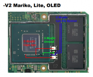
These points on the motherboard are very, very fragile, any change in temperature they come loose and break, that's the reason that made me use the NAND board test points (I thought that if I damaged something, it would be cheaper to fix it). Did you try the tip our friend @Haseo13 gave us?

Not yet but i will.... tomorrow....i'm stressed enought to try kkk but thanks very much
 
  • Like
Reactions: Jehmyson

QuiTim

Well-Known Member
Member
Joined
Mar 30, 2023
Messages
756
Trophies
0
XP
1,161
Country
Albania
I don't remember if it was this thread or other picofly one.
* What pin/pins can I disconnect to use the switch lite in the meantime while I wait for a few more supplies?
My girl is complaining about her animal crossing town :D. Trying to solder these tiny Mosfet's while trying to hold them with tweezers is killing me. I have everything wired but getting CPU error.
* Will this Mosfet (IRF8714TRPBF) work as a replacement? Someone mentioned a similar one.
I have a great soldering station but my flux and solder aren't working for this application.
* What are recommendations for those?
Currently, using Sn60/Pb40 Solder and MG Chemicals 8361 No Clean Flux
Thanks
This has mostly been answered so i'm just putting my 2 cents.
The main thing here (at least for me) is having the right size iron tip.
So, first hold the mosfet down by some fine tweezers or a needle if you have to, then add flux to mosfet, add solder to iron and tin the mosfet.
Then tin the wire and while holding the mosfet with the same wire in place just give it a quick touch with iron and it should be in place. Repeat the procedure for the other 2 wires.
Sn63Pb37 is better in my opinion, and Sn62Pb36Ag2 is the best i've used so far.
For flux i'm using MG 8341, it works fine still waiting to get my hands on some AMtech 559 (people swear by it apparently)
And yes, the 8714 works, i used it myself, much easier to work with.
Good luck
 

Type_O_Dev

Developer
Developer
Joined
Dec 12, 2017
Messages
683
Trophies
0
XP
1,469
Country
United States
This has mostly been answered so i'm just putting my 2 cents.
The main thing here (at least for me) is having the right size iron tip.
So, first hold the mosfet down by some fine tweezers or a needle if you have to, then add flux to mosfet, add solder to iron and tin the mosfet.
Then tin the wire and while holding the mosfet with the same wire in place just give it a quick touch with iron and it should be in place. Repeat the procedure for the other 2 wires.
Sn63Pb37 is better in my opinion, and Sn62Pb36Ag2 is the best i've used so far.
For flux i'm using MG 8341, it works fine still waiting to get my hands on some AMtech 559 (people swear by it apparently)
And yes, the 8714 works, i used it myself, much easier to work with.
Good luck
Hey appreciate your response. I am using “I” tip but originally wasn't, Definitely helped. I am going at it again with the original FET and hoping with I will get it, This time I'm just running 2 maybe my switch is being temperamental with one. If I don't get it today I will try the larger ones. Thanks Again!
 

QuiTim

Well-Known Member
Member
Joined
Mar 30, 2023
Messages
756
Trophies
0
XP
1,161
Country
Albania
Hey appreciate your response. I am using “I” tip but originally wasn't, Definitely helped. I am going at it again with the original FET and hoping with I will get it, This time I'm just running 2 maybe my switch is being temperamental with one. If I don't get it today I will try the larger ones. Thanks Again!
No problem.
One more thing, use more heat for short period of time instead of low heat for longer period.
This way you should get better results and less risk of damaging any component or traces.
 
  • Like
Reactions: Jehmyson

Type_O_Dev

Developer
Developer
Joined
Dec 12, 2017
Messages
683
Trophies
0
XP
1,469
Country
United States
No problem.
One more thing, use more heat for short period of time instead of low heat for longer period.
This way you should get better results and less risk of damaging any component or traces.
Thank you all, I finally got it working. I had UV resin delivered with better solder today. I could not get this Switch Lite to work with one Mosfet. Furthermore, I added a second and finally no CPU error. I actually removed all my old wires and redid connections with coil wire. Thanks again for all the help.
 

Attachments

  • new 2.jpeg
    new 2.jpeg
    987.4 KB · Views: 34
  • new.jpg
    new.jpg
    1 MB · Views: 36

cgtchy0412

Well-Known Member
Member
Joined
Apr 26, 2023
Messages
287
Trophies
0
Age
41
XP
433
Country
Indonesia
Thank you all, I finally got it working. I had UV resin delivered with better solder today. I could not get this Switch Lite to work with one Mosfet. Furthermore, I added a second and finally no CPU error. I actually removed all my old wires and redid connections with coil wire. Thanks again for all the help.
Which mosfet you installed last, suppose its the right side. Wonder if you can try to remove the left side and see if it still work. Because in my Lite only one mosfet on the left is enough, although the mosfet (source&drain) is like 1/2 cm below the capacitor.
Whether the issue is about source/drain distance or about two signal from multiple mosfets is needed, or it just every console is specific and we dont know what the variable here.
 

Type_O_Dev

Developer
Developer
Joined
Dec 12, 2017
Messages
683
Trophies
0
XP
1,469
Country
United States
Which mosfet you installed last, suppose its the right side. Wonder if you can try to remove the left side and see if it still work. Because in my Lite only one mosfet on the left is enough, although the mosfet (source&drain) is like 1/2 cm below the capacitor.
Whether the issue is about source/drain distance or about two signal from multiple mosfets is needed, or it just every console is specific and we dont know what the variable here.
The left/Bottom was the first one I had hooked up. I tried that one to both caps and still didn't work. Literally in the last 3–4 days I tried everything including left side of cap like pic in OP, but this lite would not boot with one.
 
  • Like
Reactions: Phantomas77

Takezo-San

Well-Known Member
Member
Joined
May 3, 2023
Messages
261
Trophies
0
Age
39
XP
349
Country
Seychelles
Thank you all, I finally got it working. I had UV resin delivered with better solder today. I could not get this Switch Lite to work with one Mosfet. Furthermore, I added a second and finally no CPU error. I actually removed all my old wires and redid connections with coil wire. Thanks again for all the help.
First of congrats. Question though, how come you opted to ground your source away from the APU ground point? And second, am I correct in saying, you have to combine the MOSFETs together by solder bridging them together at the source points!? (It was my only source of confusion with doubling up MOSFETs and would be a big help to clarify this for me.)
 

Attachments

  • mosfets.png
    mosfets.png
    181.6 KB · Views: 47
  • Like
Reactions: Type_O_Dev

QuiTim

Well-Known Member
Member
Joined
Mar 30, 2023
Messages
756
Trophies
0
XP
1,161
Country
Albania
First of congrats. Question though, how come you opted to ground your source away from the APU ground point? And second, am I correct in saying, you have to combine the MOSFETs together by solder bridging them together at the source points!? (It was my only source of confusion with doubling up MOSFETs and would be a big help to clarify this for me.)
You can ground them wherever you want but closer to APU is better (shorter wires, less interference and all)
Also you can combine the mosfets in all points source-to-source, drain-to-drain and gate-to-gate, its just that this setup (as seen in photo) is better from the logistics part because using only one wire to connects both drain terminals and both capacitors would be a real challange. So you bridge source (it also keeps mosfets together) then run separate wires drain-to-cap.
 

QuiTim

Well-Known Member
Member
Joined
Mar 30, 2023
Messages
756
Trophies
0
XP
1,161
Country
Albania
Thanks, do you understand why in some cases its acceptable to remove the cap and solder the mosfet directly to one of the pads?
The only reason to remove the cap is if you can not solder to it (bad iron or technique) or if you damage the capacitor by mistake.
As @Haseo13 said, better use wire when possible.
 

CodyRoseman

Active Member
Newcomer
Joined
Apr 27, 2023
Messages
41
Trophies
0
Age
27
XP
101
Country
Australia
Does the capacitor not serve an important function for the cpu, power filtering etc. There is surely some long term risk in not having it installed I'm guessing
 

Takezo-San

Well-Known Member
Member
Joined
May 3, 2023
Messages
261
Trophies
0
Age
39
XP
349
Country
Seychelles
Does the capacitor not serve an important function for the cpu, power filtering etc. There is surely some long term risk in not having it installed I'm guessing
As far as I remember, losing one or two caps on the switch would mean you shouldn't try to overclock the system down the road but other than that, it should perform fine (but don't remove them if you don't have to is the bottom line).
 

Site & Scene News

Popular threads in this forum

General chit-chat
Help Users
  • No one is chatting at the moment.
    haddad @ haddad: anyone online can help me with my new 2ds xl please...