Ps5 edm-020 no life

Dawesy72

New Member
OP
Newbie
Joined
Mar 6, 2023
Messages
2
Trophies
0
Age
52
XP
65
Country
United Kingdom
Hi. Hoping someone can help.
I have a PS5 EDM-020. No sign of life, no beeps. 12v to the board. Tested about and I have 5v and F7002 is good.
I have no 3.3v.
Tested the caps at 7002 and they show short to ground.
Removed them and the 8 pin ic, still short and caps hood out of circuit.
Flipped the board and tested apu side.
F7003 is good but showing short on caps. Removed the caps and the square chip and the component just below the caps. Still short.
Not sure where to go next. Can’t find any shorts around the south bridge but caps below APU show short which is worrying.
Checked for Liquid Metal leaks, all ok.
Any help appreciated.
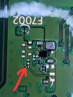
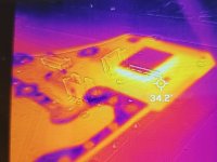
0A422385-6C2E-4BF6-B6AC-D2E1A331F070.jpeg
A1C14999-6203-4032-BF12-66E37D6345C4.jpeg
 

jkyoho

Well-Known Member
Member
Joined
Sep 2, 2020
Messages
1,285
Trophies
0
Age
39
Location
TORONTO
Website
form.jotform.com
XP
2,219
Country
Canada
I have another EDM-020 PS5 came in recently as no power. Quickly measured around and foung 5v main rail short, turned out was simple short cap around rear usb mosfet. Meanwhile looking at this EDM-020 board, I found the "02C" STEP-DOWN chip is replaced with "A2" mark chipset by Sony(possible new batch random supplier),
Soon I lookup online and found this "A2" step-down chip is TPS62822DLCT by Ti.
I don't have "02c" design EDM-020 board by hand, so I can't confirm if this "A2" is a drop in replacement for "02C". If anyone has "02C" by hand, please measure the CPU side, "02C" surrounding resistors value, I will compare them with mine.

UPDATEs:
Confirmed this "A2" TPS62822DLCT replacement is a drop-in straight replacing "02x" CHIP

TPS62822DLCR.png
 
Last edited by jkyoho,

TheWizard69

Well-Known Member
Newcomer
Joined
May 12, 2023
Messages
46
Trophies
0
Age
46
XP
125
Country
United States
I have another EDM-020 PS5 came in recently as no power. Quickly measured around and foung 5v main rail short, turned out was simple short cap around rear usb mosfet. Meanwhile looking at this EDM-020 board, I found the "02C" STEP-DOWN chip is replaced with "A2" mark chipset by Sony(possible new batch random supplier),
Soon I lookup online and found this "A2" step-down chip is TPS62822DLCT by Ti.
I don't have "02c" design EDM-020 board by hand, so I can't confirm if this "A2" is a drop in replacement for "02C". If anyone has "02C" by hand, please measure the CPU side, "02C" surrounding resistors value, I will compare them with mine.

UPDATEs:
Confirmed this "A2" TPS62822DLCT replacement is a drop-in straight replacing "02x" CHIP

Jkyoho,
Did you ever get the edm-020 you refer to in this post fixed? I have the same issue that Dawesy72 mentions in initial post. I have replaced the a2 chip on both apu and cpu side of board. Have even removed inductor and caps. Short remains. When i use thermal cam. The only thing getting hot is in the f7002 area and the backside of wifi module. Any ideas?
 
Last edited by TheWizard69,

jkyoho

Well-Known Member
Member
Joined
Sep 2, 2020
Messages
1,285
Trophies
0
Age
39
Location
TORONTO
Website
form.jotform.com
XP
2,219
Country
Canada
EDM-020 model has quite few boards came in having 3.3v or 1.8v caps short under wifi chip module. That might be your case. I had them all fixed but rarely seen a2 chip goes bad.
 

TheWizard69

Well-Known Member
Newcomer
Joined
May 12, 2023
Messages
46
Trophies
0
Age
46
XP
125
Country
United States
EDM-020 model has quite few boards came in having 3.3v or 1.8v caps short under wifi chip module. That might be your case. I had them all fixed but rarely seen a2 chip goes bad.
I have readings on all of them caps. Either 1.8 or 3.3. When supplying 12v @ 1a from bench power supply. The board draws 30ma and that is it. Thermal cam shows under the wifi module getting hot and the F7002 area. While checking voltage. Just as soon as i touch the positive side of that second cap in line for the F7002 circuit. The bench supply beeps and goes into protection mode. So frustrating without schematic hehe
 

TheWizard69

Well-Known Member
Newcomer
Joined
May 12, 2023
Messages
46
Trophies
0
Age
46
XP
125
Country
United States
I have readings on all of them caps. Either 1.8 or 3.3. When supplying 12v @ 1a from bench power supply. The board draws 30ma and that is it. Thermal cam shows under the wifi module getting hot and the F7002 area. While checking voltage. Just as soon as i touch the positive side of that second cap in line for the F7002 circuit. The bench supply beeps and goes into protection mode. So frustrating without schematic hehe
Jkyoho,
Any ideas?
 

TheWizard69

Well-Known Member
Newcomer
Joined
May 12, 2023
Messages
46
Trophies
0
Age
46
XP
125
Country
United States
I would still think 1.8v line maybe short, F7002 is where 1.8V generated by by the "02x/A2" CHIP. it wont get hot when in standby before power button press.
Do you know the value of all these caps under the wifi module? Because i will order them and replace them at this point haha any ideas?
 

TheWizard69

Well-Known Member
Newcomer
Joined
May 12, 2023
Messages
46
Trophies
0
Age
46
XP
125
Country
United States
20% X5R as standard unless you wanna pay extra $$ for the 10% specs
Okay i will get some ordered and keep you posted. Thanks!
Post automatically merged:

Okay i will get some ordered and keep you posted. Thanks!
J
Jkyoho,
For the smaller 0.1uf that would be 0201 case code right? It would not be 0402.
 
Last edited by TheWizard69,

TheWizard69

Well-Known Member
Newcomer
Joined
May 12, 2023
Messages
46
Trophies
0
Age
46
XP
125
Country
United States
Jkyoho,
I replaced all the caps under the WiFI module. Still same issue. Some caps located on that circuit show short to ground in continuity mode. But all caps either read a 1.8v or 3.3v in voltage mode. Known good board does not read short in continuity mode upon measuring the same caps. I am wondering if i have a bad wifi module. Where does the 3.3 volt power rail come in? Any ideas?
Jkyoho,
Sorry to keep calling on you. I trust your opinion and guidance. Take it as a compliment hehe. :) I replaced both step down converters with known good TPS62822DLCR's. Used a thermal cam prior to replacement and the only thing heating up was the wifi and F7002 chip area. I had a very low reistance to ground on the resistor that should be where the arrow points. Decided to replace this. Board produces same thermal cam results with resistor not in place. Any ideas on the value of this resistor? Currently the board will draw 55ma then drop immediately down to 24ma. This is an edm-020 board. I have attached a couple pics for reference. Any help would be greatly appreciated.
 

Attachments

  • 20230829_214017.jpg
    20230829_214017.jpg
    820 KB · Views: 80
  • 20230829_215606.jpg
    20230829_215606.jpg
    1.8 MB · Views: 62
  • 20230829_215546.jpg
    20230829_215546.jpg
    1.2 MB · Views: 68

jkyoho

Well-Known Member
Member
Joined
Sep 2, 2020
Messages
1,285
Trophies
0
Age
39
Location
TORONTO
Website
form.jotform.com
XP
2,219
Country
Canada
Jkyoho,
Sorry to keep calling on you. I trust your opinion and guidance. Take it as a compliment hehe. :) I replaced both step down converters with known good TPS62822DLCR's. Used a thermal cam prior to replacement and the only thing heating up was the wifi and F7002 chip area. I had a very low reistance to ground on the resistor that should be where the arrow points. Decided to replace this. Board produces same thermal cam results with resistor not in place. Any ideas on the value of this resistor? Currently the board will draw 55ma then drop immediately down to 24ma. This is an edm-020 board. I have attached a couple pics for reference. Any help would be greatly appreciated.
The red arrow resistor is on the 1.8v line where the TPS generated, so is some of the capacitor under WIFI chip on same 1.8v line. If you could inject voltage(less than 1.8v), I would suggest you use the gold test pad in yellow square mark and see what exactly heats up.
FYI, I dont have the measured value around F7002, sorry.
 

Attachments

  • 1693364726982.png
    1693364726982.png
    6.6 MB · Views: 62

TheWizard69

Well-Known Member
Newcomer
Joined
May 12, 2023
Messages
46
Trophies
0
Age
46
XP
125
Country
United States
The red arrow resistor is on the 1.8v line where the TPS generated, so is some of the capacitor under WIFI chip on same 1.8v line. If you could inject voltage(less than 1.8v), I would suggest you use the gold test pad in yellow square mark and see what exactly heats up.
FYI, I dont have the measured value around F7002, sorry.
Thank you for replying. Sounds logical to me. I remember i injected voltage to the first cap where the 1.8 and it popped the fuse. This was before i replaced the wifi module. So i will give this a go and report back. Much appreciated. :)
Post automatically merged:

Thank you for replying. Sounds logical to me. I remember i injected voltage to the first cap where the 1.8 and it popped the fuse. This was before i replaced the wifi module. So i will give this a go and report back. Much appreciated. :)
Nothing is getting hot. Injected 1.0, 1.2, 1.3v @ 1.0a current. This is such a needle in a haystack.
 
Last edited by TheWizard69,

Site & Scene News

Popular threads in this forum

General chit-chat
Help Users
    BigOnYa @ BigOnYa: https://youtu.be/l6ek7TmdGE8?si=k_qXsn8Finqhz70P +1