Jkyoho,
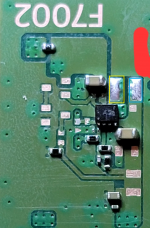
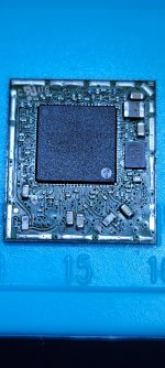
I re-balled the 2nd replacement wifi module and soldered back to board. But this time I left the shield off the module so I could take readings from components directly on the wifi module. I have my 3.3 on the test point located on the motherboard. I also have 3.3 and 1.8 on the caps for the wifi module itself. The only time the f7002 circuit reads a short is when the wifi module is soldered to the board. If its removed the diode readings for the f7002 circuit go back to normal. The short also exists on the caps on opposite side of wifi module. But those shorts go away as well when the wifi module is removed. I feel like i am running in circles with this one. I checked the southbridge and i have good diode readings there as well. I also have good readings at hdmi encoder. Any ideas?


")