


sure find the pins with a multimeter and a flex cableHello. Is there a way to turn on an OLED board by shorting the power pins' slot? I got one that I think is alive and would like to get it picoflyed.
You are using an out of date browser. It may not display this or other websites correctly.
You should upgrade or use an alternative browser.
You should upgrade or use an alternative browser.
Staff Posts
Recent threadmarks
sharing files
Important Posts
Recent threadmarks
Firmwares
Hello. Is there a way to turn on an OLED board by shorting the power pins' slot? I got one that I think is alive and would like to get it picoflyed.
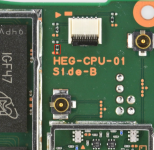
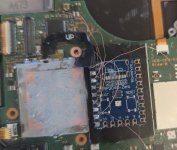
this is the test pad for the power button on the oled pcb. you can short it to the screw hole above with a pair of tweezers to turn the console on and off.
this is the test pad for the power button on the oled pcb. you can short it to the screw hole above with a pair of tweezers to turn the console on and off.
View attachment 384511
sure find the pins with a multimeter and a flex cable
Thank you brothers<3. Now if you excuse me, I gotta an OLED that needs saving
")
- Joined
- Sep 2, 2020
- Messages
- 1,342
- Trophies
- 0
- Age
- 39
- Location
- TORONTO
- Website
- form.jotform.com
- XP
- 2,277
- Country

Shorting this resistor to ground should also do the trick.Hello. Is there a way to turn on an OLED board by shorting the power pins' slot? I got one that I think is alive and would like to get it picoflyed.
Attachments
ur gonna have to try to find the original traces it was connected to , so in other words ur gonna have to slowley scratch of the top layers of the apu to find the existing layers
Post automatically merged:
but im pretty sure this is gonna be impossible , give me a sec im gonna show u a picture why
Post automatically merged:
Post automatically merged:
i took a defective Apu from a v2 its the same as on the oled and grinded the layers down fast so u can see what u would be dealing with and why this is pretty much not possible for u even i would try it cause its a wast of time and effort
View attachment 384506
red top layer (Uvmask)
Black second layer ground
third layer is pcb material
Blue fourth layer ground
green via in forth layer
Post automatically merged:
More of the fourth layer
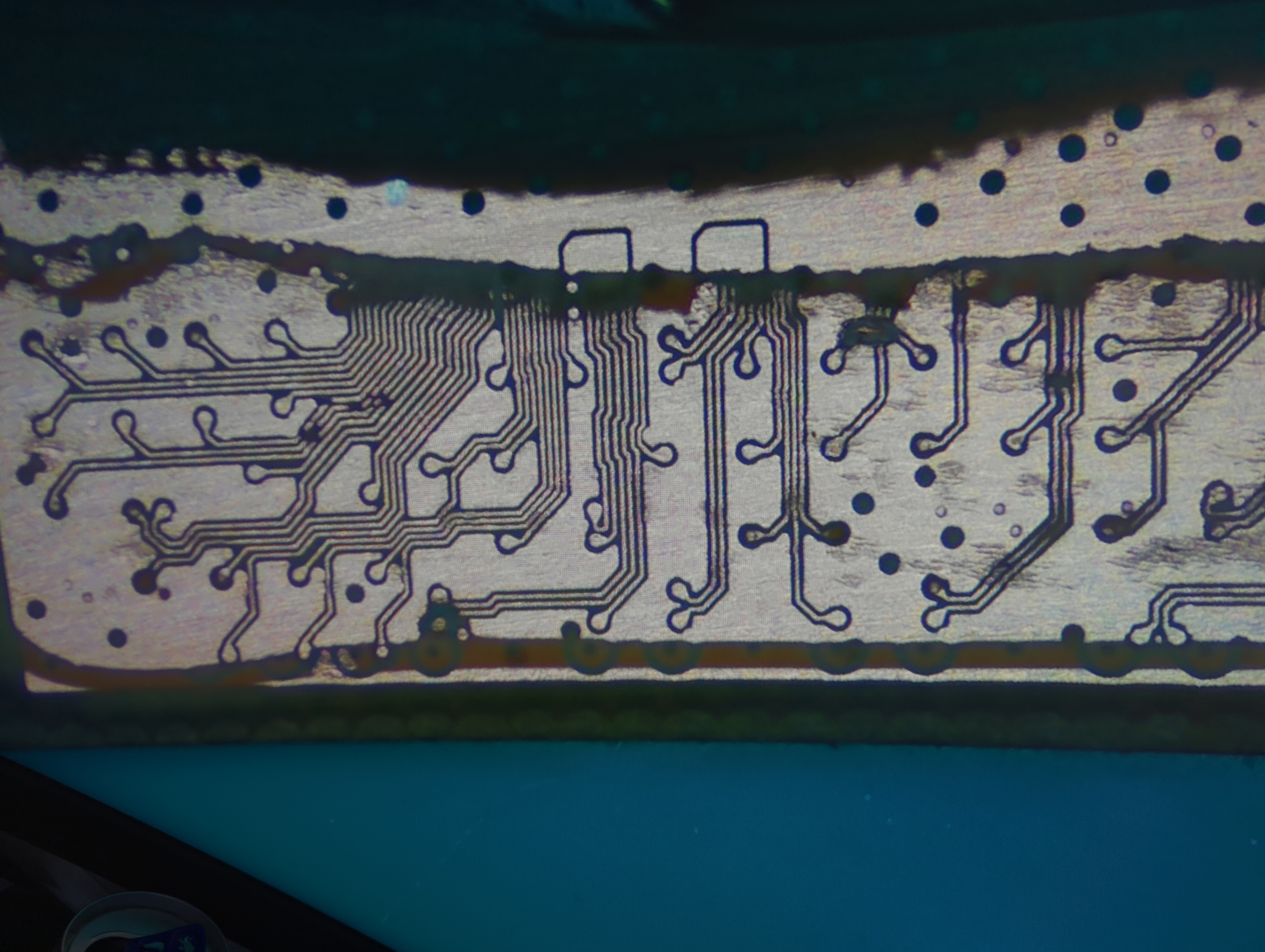
this is the sixth layer after that they appear to go to the solderjoints under the apu
View attachment 384508
You are very informative. Thanks for doing this for me as I would not have accepted this was beyond my scope without the pictures. Guess I will try again on a different switch.
Any recommendations for cutting tool so I don't have this problem again?
no problem im gonna be honest i just thought ill grind to the first 2 layers very fast to show u its pretty much undoable by hand, but then i wanted to see how many layers there are XdYou are very informative. Thanks for doing this for me as I would not have accepted this was beyond my scope without the pictures. Guess I will try again on a different switch.
Any recommendations for cutting tool so I don't have this problem again?
ClickMe flush cutters like this one
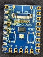
oh and dont forget to get the rp2040-zero if u need support ;-) but i would recommend u the rp2040 tiny since they dont have a usb onboard and already have the resistors on the board u flash them with a flex cable and they are also supported :-)

These are back in stock (I dont know how many) https://www.tindie.com/products/ignas/emmc-reader-for-hac-emmc/
just an update for some of you who wanted to buy this before but it was sold out.
Also, for those of you who worry about thermal issues after removing the red paste and replacing it with normal one, I just got my hands on this https://amzn.eu/d/adkUgpn and it's great stuff, never seen something like this before. (thanks @vagenam for this)
Hm, I just realized the left joycon doesn't charge and it's not actually connected to the rail - I hadn't noticed it because it was already paired and still works wirelessly. Which part of the board takes care of that? I'll have to go back in and fix it.

Are you sure it isn't just a bad rail?Hm, I just realized the left joycon doesn't charge and it's not actually connected to the rail - I hadn't noticed it because it was already paired and still works wirelessly. Which part of the board takes care of that? I'll have to go back in and fix it.
Seeing as it's brand new and was working right before the mod, I don't think so, prob something I did when installing the pico. Just want to know where it's likely I need to poke around.Are you sure it isn't just a bad rail?
Then u didn't properly connect all flex cables I would guess open it up and see which one isn't connected properly ;-)Hm, I just realized the left joycon doesn't charge and it's not actually connected to the rail - I hadn't noticed it because it was already paired and still works wirelessly. Which part of the board takes care of that? I'll have to go back in and fix it.

Hm, I just realized the left joycon doesn't charge and it's not actually connected to the rail - I hadn't noticed it because it was already paired and still works wirelessly. Which part of the board takes care of that? I'll have to go back in and fix it.
the flat ribbon cable next to the battery connector
flashed a rp2040 w/ picofly and installed it, it bootsI understand your frustration with the existence and use of these chips and I agree. I have a few RP2040 dev boards lying around so I will prepare and install my own RP2040 board soon then, just need to get resistors. If the LED error still happens after replacement I will ask for support here hopefully without getting dogpiled for using h***y in the past lol. At the very least it came with the MOSFET flex
Honest mistake, it isn't stated anywhere obvious at the start of the thread (likely b/c this was a speculation-turned-support thread from what I can tell) and I didn't explicitly see anyone say those boards are not supported when reading through earlier, I was not aware when writing, sorry!
once i replace the chip w/ my own rp2040 & use thicker AWG i will try to remember to report back with results
but **= error still happens a little more rarely now.I got rid of the FPCB that connects 3.3v, clk, cmd etc. to a ribbon cable as i do not need it anymore.
Booted the Switch about 60 times, 2 times the LED codes showed again. I missed the first LED code but the second one was **= which is 'No eMMC block 1 read (should not happen)' which is one of the two codes I got before.
I have a feeling/I kinda hope it is just the wires I'm using, my wires are thinner than recommended and they are enameled/magnet wire so i wouldn't be surprised if i like, tapped the length of a wire with my iron by accident and it is shorting with something.
I'm using the same 38AWG wire all points including the 3.3v and ground, I am going to replace them with 30AWG once I receive it. Is 38AWG too thin to use for these lines, even temporarily? I will undo them and wait until I get the proper wire if so.
I was having that 2002-3539 error on OFW after initial install, I doubt it's related but I don't wanna fully rule it out. It thankfully hasn't happened since I swapped DAT0 adapters and leaving the Switch on overnight in-game twice to confirm that the issue is gone for 'good'. Could it have possibly corrupted the eMMC block 1? It boots into OFW no problem with or without the modchip so idk. I have backups of BOOT0/1. eMMC and keys ofc.
Attached pictures of my dirty yet prepared rp2040 w/ resistors, the switch itself and 'install' pictures. The 'install' picture was taken after first boot, after that I desoldered everything and routed all the wires properly and got rid of slack + reflowed the points on the RP2040 to get rid of the cold joints. I used magnet/enameled copper wire, so they should be insulated but I am going to replace them anyways when I receive 36AWG and 30AWG wire in the mail. I will take new pictures of the install at that point as well. I put a layer of electrical tape over the RAM part of the heat spreader for the underside of the RP2040 and layered Kapton tape on the underside of the metal shielding that would touch the top of the RP2040 to prevent shorts.
Thanks for reading
Attachments
ofw can be unstable because of the 47ohm resistors on dat0/cmd, which is why many of us use 100 ohm instead. if you dont have any 100ohm resistors you can add another 47ohm to achieve 47+47=94ohmflashed a rp2040 w/ picofly and installed it, it boots
I got rid of the FPCB that connects 3.3v, clk, cmd etc. to a ribbon cable as i do not need it anymore.
Booted the Switch about 60 times, 2 times the LED codes showed again. I missed the first LED code but the second one was **= which is 'No eMMC block 1 read (should not happen)' which is one of the two codes I got before.
I have a feeling/I kinda hope it is just the wires I'm using, my wires are thinner than recommended and they are enameled/magnet wire so i wouldn't be surprised if i like, tapped the length of a wire with my iron by accident and it is shorting with something.
I'm using the same 38AWG wire all points including the 3.3v and ground, I am going to replace them with 30AWG once I receive it. Is 38AWG too thin to use for these lines, even temporarily? I will undo them and wait until I get the proper wire if so.
I was having that 2002-3539 error on OFW after initial install, I doubt it's related but I don't wanna fully rule it out. It thankfully hasn't happened since I swapped DAT0 adapters and leaving the Switch on overnight in-game twice to confirm that the issue is gone for 'good'. Could it have possibly corrupted the eMMC block 1? It boots into OFW no problem with or without the modchip so idk. I have backups of BOOT0/1. eMMC and keys ofc.
Attached pictures of my dirty yet prepared rp2040 w/ resistors, the switch itself and 'install' pictures. The 'install' picture was taken after first boot, after that I desoldered everything and routed all the wires properly and got rid of slack + reflowed the points on the RP2040 to get rid of the cold joints. I used magnet/enameled copper wire, so they should be insulated but I am going to replace them anyways when I receive 36AWG and 30AWG wire in the mail. I will take new pictures of the install at that point as well. I put a layer of electrical tape over the RAM part of the heat spreader for the underside of the RP2040 and layered Kapton tape on the underside of the metal shielding that would touch the top of the RP2040 to prevent shorts.
Thanks for reading
This was literally it lmao, I did put the console back together at like 4AM, so that explains the obvious mistake. Thanks.Then u didn't properly connect all flex cables I would guess open it up and see which one isn't connected properly ;-)
added another 47ohm resistor onto dat0 and cmd, was initially able to boot around 50 times without fail but after screwing the shield onto the back i got the **= error again. unscrewed it, powered the switch back on, booted no problem. kept the shield off, kept on rebooting for a while to test and eventually got the **= error again. simply powering off the switch and rebooting is enough to make the chip correctly boot again. In other cases, it requires like 2 reboots.ofw can be unstable because of the 47ohm resistors on dat0/cmd, which is why many of us use 100 ohm instead. if you dont have any 100ohm resistors you can add another 47ohm to achieve 47+47=94ohm
at this point im almost certain its wire interference/shorting related as adding the resistors didn't fix it but it did seem to help. I did however use the one kind of wire that could cause shorts that are practically invisible so im leaning towards that being the culprit
ordered non-enameled 'proper' (im sure theres a better term) 36awg and 30awg wire, gonna replace the dat0 wire (as it seems related to dat0 ofc) and 3.3v/ground wires as soon as i can and see if that gets rid of the problem for good

Hi everybody, I am looking for some help here.
Long story short: I soldered the hwfly rp2040 (but basically is a clone based on picofly) and after after some problems, i got to a state where the modchip booted to the "No sd card" screen. So I was ready to close it.
I did various power-on tests while closing it. Until the metal cover was closed, it worked (booting to the screen mentioned). The moment I closed the black cover, the switch no longer turned on.
I disassembled everything, the modchip gives the following error (with led blinking): *== No eMMC CMD1 request (poor wiring, or dead CPU)
I'm posting screenshots, but basically I covered the metal plate where to allocate the modchip with kapton tape. I have also cut the cover to accommodate it. I have the impression that when closing, the modchip touched somehow the emmc board, which was not protected with kapton. Or something else. Also, I didn't even put the kapton above the capacitor soldered to the adapter (but I don't think it touched the metal cover).
So I unsoldered everything, cleaned the CPU, inserted the emmc in the original housing. Nothing, black screen here too.
A user in the other post assumes a problem with the emmc, probably hardware.
When I press the power button and the modchip powers up, that's why I talk about "black screen".
I also have a thread with additional info and photos: https://gbatemp.net/threads/black-s...witch-with-hwfly-rp2040.636599/#post-10208691
Hope someone can help me in figuring this out.
Thanks in advance!
If u need help with ur hwfly chip use ur own thread but dont hijack a picofly cause its "basicly" the same.Hi everybody, I am looking for some help here.
Long story short: I soldered the hwfly rp2040 (but basically is a clone based on picofly) and after after some problems, i got to a state where the modchip booted to the "No sd card" screen. So I was ready to close it.
I did various power-on tests while closing it. Until the metal cover was closed, it worked (booting to the screen mentioned). The moment I closed the black cover, the switch no longer turned on.
I disassembled everything, the modchip gives the following error (with led blinking): *== No eMMC CMD1 request (poor wiring, or dead CPU)
I'm posting screenshots, but basically I covered the metal plate where to allocate the modchip with kapton tape. I have also cut the cover to accommodate it. I have the impression that when closing, the modchip touched somehow the emmc board, which was not protected with kapton. Or something else. Also, I didn't even put the kapton above the capacitor soldered to the adapter (but I don't think it touched the metal cover).
So I unsoldered everything, cleaned the CPU, inserted the emmc in the original housing. Nothing, black screen here too.
A user in the other post assumes a problem with the emmc, probably hardware.
When I press the power button and the modchip powers up, that's why I talk about "black screen".
I also have a thread with additional info and photos: https://gbatemp.net/threads/black-s...witch-with-hwfly-rp2040.636599/#post-10208691
Hope someone can help me in figuring this out.
Thanks in advance!
Hwfly chips are not supported in this thread its been explained probally 1000 times.
why dont u ask ur chip supplier for help since he created and send it out preflashed ? so he should do ur support
since u have ur own thread use that thread ....................

Forward this message to your hwfly seller. They're way more helpful than this thread. Trust me. You'll be up and running in no time.Hi everybody, I am looking for some help here.
Long story short: I soldered the hwfly rp2040 (but basically is a clone based on picofly) and after after some problems, i got to a state where the modchip booted to the "No sd card" screen. So I was ready to close it.
I did various power-on tests while closing it. Until the metal cover was closed, it worked (booting to the screen mentioned). The moment I closed the black cover, the switch no longer turned on.
I disassembled everything, the modchip gives the following error (with led blinking): *== No eMMC CMD1 request (poor wiring, or dead CPU)
I'm posting screenshots, but basically I covered the metal plate where to allocate the modchip with kapton tape. I have also cut the cover to accommodate it. I have the impression that when closing, the modchip touched somehow the emmc board, which was not protected with kapton. Or something else. Also, I didn't even put the kapton above the capacitor soldered to the adapter (but I don't think it touched the metal cover).
So I unsoldered everything, cleaned the CPU, inserted the emmc in the original housing. Nothing, black screen here too.
A user in the other post assumes a problem with the emmc, probably hardware.
When I press the power button and the modchip powers up, that's why I talk about "black screen".
I also have a thread with additional info and photos: https://gbatemp.net/threads/black-s...witch-with-hwfly-rp2040.636599/#post-10208691
Hope someone can help me in figuring this out.
Thanks in advance!

Try to touch/rub all solder point on pico with finger, any sharp? protude? thats will make a short if you screw the shield.added another 47ohm resistor onto dat0 and cmd, was initially able to boot around 50 times without fail but after screwing the shield onto the back i got the **= error again. unscrewed it, powered the switch back on, booted no problem. kept the shield off, kept on rebooting for a while to test and eventually got the **= error again. simply powering off the switch and rebooting is enough to make the chip correctly boot again. In other cases, it requires like 2 reboots.
at this point im almost certain its wire interference/shorting related as adding the resistors didn't fix it but it did seem to help. I did however use the one kind of wire that could cause shorts that are practically invisible so im leaning towards that being the culprit
ordered non-enameled 'proper' (im sure theres a better term) 36awg and 30awg wire, gonna replace the dat0 wire (as it seems related to dat0 ofc) and 3.3v/ground wires as soon as i can and see if that gets rid of the problem for good
Similar threads
- Replies
- 5
- Views
- 2K
- Replies
- 2
- Views
- 838
- Replies
- 42
- Views
- 7K
Site & Scene News
New Hot Discussed
-
-
39K views
New static recompiler tool N64Recomp aims to seamlessly modernize N64 games
As each year passes, retro games become harder and harder to play, as the physical media begins to fall apart and becomes more difficult and expensive to obtain. The... -
18K views
Majora’s Mask PC port 2Ship2Harkinian gets its first release
After several months of work, the Harbour Masters 64 team have released their first public build of 2Ship2Harkinian, a feature-rich Majora's Mask PC port. This comes... -
17K views
Anbernic reveals the RG35XXSP, a GBA SP-inspired retro handheld
Retro handheld manufacturer Anbernic has revealed its first clamshell device: the Anbernic RG35XXSP. As the suffix indicates, this handheld's design is inspired by... -
17K views
Mario Builder 64 is the N64's answer to Super Mario Maker
With the vast success of Super Mario Maker and its Switch sequel Super Mario Maker 2, Nintendo fans have long been calling for "Maker" titles for other iconic genres... -
13K views
The founder of Oculus is releasing a $199 FPGA Game Boy system
Palmer Luckey is known for his pursuits into the world of virtual reality, having founded Oculus and designed the Rift VR headset. Prior to the $2 billion dollar... -
13K views
Ubisoft reveals 'Assassin's Creed Shadows' which is set to launch later this year
Ubisoft has today officially revealed the next installment in the Assassin's Creed franchise: Assassin's Creed Shadows. This entry is set in late Sengoku-era Japan... -
13K views
RetroArch is now available in the Apple Store for iOS devices
Another day, another great emulator that makes its way into the Apple Store for more users to enjoy. With Apple opening its store up to videogame emulators earlier...by ShadowOne333 58 -
12K views
The Kingdom Hearts games are coming to Steam
After a little more than three years of exclusivity with the Epic Games Store, Square Enix has decided to bring their beloved Kingdom Hearts franchise to Steam. The... -
10K views
Nintendo takes down the Breath of the Wild randomizer mod from Gamebanana
Another day, another Nintendo DMCA takedown against fan-made content. Just a few minutes ago, Nintendo issued a DMCA takedown notice against a widely known and...by ShadowOne333 87 -
9K views
PS1 emulator "Gamma" has been added to the Apple Store for iOS devices
Continuing with the number of available retro emulators found in the Apple Store, after Apple's decision to finally allow videogame emulators on their store, another...by ShadowOne333 48
-
-
-
162 replies
The founder of Oculus is releasing a $199 FPGA Game Boy system
Palmer Luckey is known for his pursuits into the world of virtual reality, having founded Oculus and designed the Rift VR headset. Prior to the $2 billion dollar...by Chary -
145 replies
New static recompiler tool N64Recomp aims to seamlessly modernize N64 games
As each year passes, retro games become harder and harder to play, as the physical media begins to fall apart and becomes more difficult and expensive to obtain. The...by Chary -
104 replies
Majora’s Mask PC port 2Ship2Harkinian gets its first release
After several months of work, the Harbour Masters 64 team have released their first public build of 2Ship2Harkinian, a feature-rich Majora's Mask PC port. This comes...by Scarlet -
96 replies
Ubisoft reveals 'Assassin's Creed Shadows' which is set to launch later this year
Ubisoft has today officially revealed the next installment in the Assassin's Creed franchise: Assassin's Creed Shadows. This entry is set in late Sengoku-era Japan...by Prans -
90 replies
The Kingdom Hearts games are coming to Steam
After a little more than three years of exclusivity with the Epic Games Store, Square Enix has decided to bring their beloved Kingdom Hearts franchise to Steam. The...by Chary -
87 replies
Nintendo takes down the Breath of the Wild randomizer mod from Gamebanana
Another day, another Nintendo DMCA takedown against fan-made content. Just a few minutes ago, Nintendo issued a DMCA takedown notice against a widely known and...by ShadowOne333 -
67 replies
Select PlayStation 2 games are coming to PlayStation 5
Sony is once more attempting to reintroduce players to their older library of games by re-releasing classic PlayStation 2 titles onto the PlayStation Store. During...by Chary -
65 replies
Anbernic reveals the RG35XXSP, a GBA SP-inspired retro handheld
Retro handheld manufacturer Anbernic has revealed its first clamshell device: the Anbernic RG35XXSP. As the suffix indicates, this handheld's design is inspired by...by Prans -
65 replies
Mario Builder 64 is the N64's answer to Super Mario Maker
With the vast success of Super Mario Maker and its Switch sequel Super Mario Maker 2, Nintendo fans have long been calling for "Maker" titles for other iconic genres...by Scarlet -
63 replies
PlayStation State of Play May 2024 showcase - God of War: Ragnarok coming to PC
The latest State of Play is here. This is PlayStation's Summer showcase, providing updates to new updates on upcoming games and brand new reveals. The 35-minute...by Chary
-
Popular threads in this forum
General chit-chat
- No one is chatting at the moment.
-
-
-
-
-
-
-
-
-
 @
BigOnYa:
He was the ass of gbatemp, everyone knocked on him, I honestly felt bad, even though I was guilty myself, but he egged it all on himself,
@
BigOnYa:
He was the ass of gbatemp, everyone knocked on him, I honestly felt bad, even though I was guilty myself, but he egged it all on himself, -
-
-
@
BigOnYa:
I feel like gbatemp should make t-shirts or memorabilia to remember the lost ones. I bet the Polly shirts would sell out quick.
-
-
-
-
@
BigOnYa:
Your correct, Somebody would be guilty and there would be riots, then they storm the gbatemp capitol,
-
 @
K3Nv2:
Online or not there are still certain rights that judges would have no issue handing out a warrant over
@
K3Nv2:
Online or not there are still certain rights that judges would have no issue handing out a warrant over -
-
@
BigOnYa:
Honestly I'm scared to, from you, but ok, lemme turn on vpn, virtual machine, private browser first
-
-
-
@
BigOnYa:
That robot is here somewhere, I hear it moving around at night, but I haven't seen it for months.
-
@
BigOnYa:
Oh that laptop I give to ancientboi, so you been watching him for months, and he's been watching you
-
-