Update from me:
After a Time my Switch did not glitch at all - DAT-0-Error as previously mentioned, but now always. So i did the following:
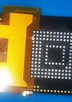
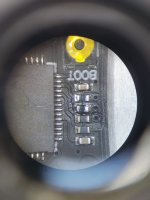
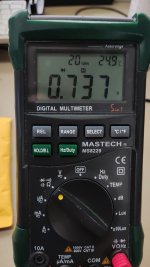
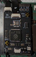
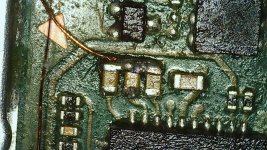
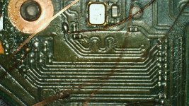
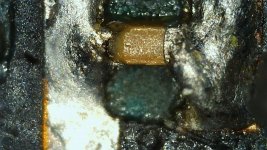
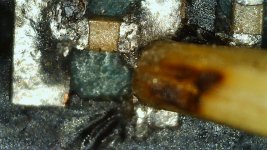
I changed the 2 Resistors to 100 OHM on my Picofly-Chip and relocated my DAT-0 Cable. I previously had it located near the Gamecard-Insert - the Cable got broken, so that was my Issue with the DAT0-Error. I measured the DAT-0 Point again on the Adapter - it´s how it should be (see Picture).
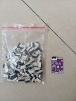
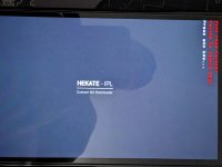
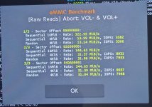
Since i did not find my specific Chip-Design in the Thread where they were discussing the Issues with the China-Clones I measured the Resistors on my Chip and checked the Values and replaced the 2 47 OHM Resistors with 100 OHM. I attached everything again - tried to boot - the Glitch worked (NO-SD-Card Screen). When pressing both Volume-Buttons it did NOT Boot to OFW. After Inserting my SD-Card it booted to HEKATE. From there I can boot to EmuNAND. I can not boot to SysNAND or to the OFW from Hekate - i get a really strange Error ("Pkg2 read failed. Failed to launch HOS") (see Pictures). I definetly did NOT have this Issue before. Before when i tried to boot OFW or SYSNAND from Hekate the Screen simply went black.
So what did i wrong now

Attached are Files from my resoldering.
I´m being honest with you all - I´m fed up with my Chip. I know it´s 100% my fault for buying this Clone and i think I will simply use the Switch as it is - EMUNAND works.
Anyone any Ideas on my Problem(s) ? Is there simply a Chip buyable where my FLEX-Cables Fit so i can simply change my Chip to a working one ?