This one will do: https://www.aliexpress.com/item/1005003995897474.htmlAnyone know where I can find a flex for a v1 Erista? I'm interested in trying this mod but my free-hand soldering isn't the best.
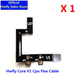
select the same one as in photo
This one will do: https://www.aliexpress.com/item/1005003995897474.htmlAnyone know where I can find a flex for a v1 Erista? I'm interested in trying this mod but my free-hand soldering isn't the best.
Awesome, thanks, and you don't need the MOSFET If you're using the flex?This one will do: LINK REMOVED CUS NEW
select the same one as in photo
Flex already has mosfet attachedAwesome, thanks, and you don't need the MOSFET If you're using the flex?
Anyone know where I can find a flex for a v1 Erista? I'm interested in trying this mod but my free-hand soldering isn't the best.
Try Aliexperss or use low cost mosfetAnyone know where I can find a flex for a v1 Erista? I'm interested in trying this mod but my free-hand soldering isn't the best.
I'm more concerned with ruining the SoC than ruining a MOSFET, I've picked up a pair of flexes for my switches, gonna grab a pair of rp2040-one nowTry Aliexperss or use low cost mosfet
Forgeting to connect the emmc did not cause this issue.Hi! My 4th picofly, have done 1 oled and 2 lites always with flex cable with no problem
Was doing a V1, measured all diode values before turn on, all good but, forgot to attach the emmc chip, turn the switch on, the chip only showed blue light and then turned off...And now doesnt turn on anymore
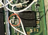
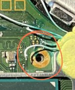
Did tried many things but since then I have a lot of shorts everywhere (red in image)
The cpu is dead right?
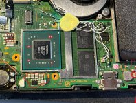
Did you check these areas?Hi! My 4th picofly, have done 1 oled and 2 lites always with flex cable with no problem
Was doing a V1, measured all diode values before turn on, all good but, forgot to attach the emmc chip, turn the switch on, the chip only showed blue light and then turned off...And now doesnt turn on anymore
Did tried many things but since then I have a lot of shorts everywhere (red in image)
The cpu is dead right?
")
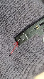
What can i do if i´ve broken all the normal pads? And which pins should i bridge? Switch doesn't boot, so i assume d0 is broken? Is it essential that the clock and cmd pads are connected too?YES YOU MUST BRIDGING THIS TWO POINTS
Add 33ohm to rst will boot faster / add 100ohm to dat0 it will help or try retrain chup by picofly toolMy install works on my lite, but it takes a long time to boot and when it does it shows a red light rather than a green one. Besdies that, its working fine and I dumped my nand with no slow mode/ any other issue, whats the cause for this?
Right. Then run a single wire from, the now bridged sources, to the ground point. And two wires from the gate points to CPU (at the pico). Got it.
Yes it is looking for a payload.bin on SD card. The PicoFly guide talks about this. You can follow any other switch cfw/atmosphere guide to allow homebrew.Hello.All videos show only chip soldering. Do I need to install something to the sd card? Or should I insert a blank formatted sd card?
Yes I use 30awg like that for my mosfets.This will work without issue for the MOSFETS on an OLED?
https://uk.rs-online.com/web/p/hook-up-wire/2094811
Just strip the ends as usual and good to go?Yes I use 30awg like that for my mosfets.
yesJust strip the ends as usual and good to go?