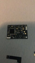
Tutorial  Updated

How to flash the HWFLY Clone chips

See below for updates.

IF YOU BREAK YOUR BOOT0 PIN. DO NOT DM ME ASKING FOR HELP. THAT'S IT. YOU BREAK THAT PIN AND YOU CANT FLASH. YOUR CHIP IS STUCK WITH WHATEVER HWFLY PUT ON IT


Pre-requisites:


  • Raspberry Pi Zero W
    • You may use another flasher if you desire.
  • Pinout Diagram
  • Modchip Diagram
  • FULL_CHIP_STOCK.bin
  • Modchip Diagram, find the PA9(TX) and the PA10(RX) pins on your modchip, and do the following:
    • Connect GPIO14(TX) on your Raspberry Pi Zero W to the PA10(RX) pin on your modchip.
    • Connect GPIO15(RX) on your Raspberry Pi Zero W to the PA9(TX) pin on your modchip.

  1. Solder a wire to each of the following pinouts on the Raspberry Pi Zero W:
    • 3.3V
    • Ground
    • GPIO 14 (UART TX)
    • GPIO 15 (UART RX)
  2. Do the following to prepare the modchip:
    1. Lift pin 44 (also known as BOOT0).
    2. You will need a way to power the chip, so you need to find two 3.3v points. It can be on a MOSFET, but it will differ based on the revision of the modchip.
    3. Connect Ground on your Raspberry Pi Zero W to the Ground pin on your modchip.
    4. Check the Modchip Diagram, find the PA9(TX) and the PA10(RX) pins on your modchip, and do the following:
      • Connect GPIO14(TX) on your Raspberry Pi Zero W to the PA10(RX) pin on your modchip.
      • Connect GPIO15(RX) on your Raspberry Pi Zero W to the PA9(TX) pin on your modchip.
  3. Boot your Raspberry Pi Zero W and do the following:
    1. In the terminal, type the following command, and press enter:
      Bash:
      sudo nano /boot/config.txt
    2. Add the following line to the end of the file:
      INI:
      dtoverlay=pi3-miniuart-bt
    3. Press CTRL + X to save and exit the editor.
    4. In the terminal, type the following command, and press enter:
      Bash:
      sudo nano /boot/cmdline.txt
    5. Remove the following line from the file:
      INI:
      console=serial0,115200
    6. Press CTRL + X to save and exit the editor.
    7. Restart your Raspberry Pi with this command
      Bash:
      sudo /sbin/reboot
    8. In the terminal, type the following commands, and press enter after each command:

      Bash:
      git clone https://github.com/Pheeeeenom/stm32flash.git
      cd stm32flash
      sudo make install
  4. Now you will flash the modchip.
    Note: This will remove read protection, and the modchip will wipe itself (that is what we want).
    1. In the terminal, type the following command, and press enter:
      Bash:
      stm32flash -k /dev/serial0
    2. Now to flash Spacecraft-NX Version 0.2.0, type the following, and press enter:
      Bash:
      stm32flash -v -w ./FULL_CHIP_STOCK.bin /dev/serial0
  5. Once you're done flashing your modchip, remove the wiring from the modchip, and restore the 3.3v pin on the modchip to its original position.

Please post pictures of your work here to further the identification of the different board revisions!


UPDATE: So it seems like stitching the spacecraft bootloader and firmware together from the repo causes unstable glitching behaviors. For now, consistent glitching behavior works with this bootload/firmware combo.
This is the original file on the OLED variant chip which has 0.2.0 spacecraft. As for glitching, I'll figure it out, give me some time...unless someone else wants to hop in and reverse the differences.

For now, this at least solves the 0.1.0 HWFLY gen 3 issue. More to come.

UPDATE 2: This is only going to work on some HWFLY chips. Older ones use higher protection than the new revisions that seem to use the QFN FPGA.

UPDATE 3: This should fully work on OLED modchips with the QFN FPGA. https://github.com/Pheeeeenom/firmware
 
Last edited by Mena,

FruithatMods

Well-Known Member
Member
Joined
Dec 16, 2018
Messages
128
Trophies
0
Age
34
XP
450
Country
Germany
Is this a 5 volt chip which will brick the switch or is this a 3.3v?

The seller says it is on spacecraft 0.2.0. Does that sound right or does the fw need to be updated?
 

Attachments

  • IMG-20220222-WA0006.jpg
    IMG-20220222-WA0006.jpg
    213.6 KB · Views: 50

doom95

Well-Known Member
Member
Joined
Aug 12, 2019
Messages
303
Trophies
0
Age
24
XP
785
Country
Netherlands
yes you can update it but there is no firmware for it.
although the microcontroller is identical, the fpga is different and the protocol between microcontroller and fpga has changed, but this is undocumented
 

Quezacotl

Well-Known Member
Newcomer
Joined
Aug 12, 2020
Messages
69
Trophies
0
Age
37
XP
235
Country
Finland
What is the BOOT0 pin lifting about? There's nothing else on the guide but "lift boot0"
I'm able to write the chip without doing anything to BOOT0.

I have a problem. I have SX Core, very most likely a clone, and it has been flashed with USB, but after that, it doesn't respond to it at all. It's completely dead except it gives solid green LED when it's powered by ST-Link, Switch or bench supply. And needless to say, it doesn't do anything with the Switch.
It doesn't matter what i flash it with. If i flash the stock image from the first post, it goes bricked even more, and fiddling with reset i can luckily get it back from total brick. I can see that some bootloaders i try to flash give solid LED and some just give nothing.
 

kylum

Well-Known Member
Member
Joined
Dec 8, 2008
Messages
394
Trophies
1
XP
1,481
Country
United States
What is the BOOT0 pin lifting about? There's nothing else on the guide but "lift boot0"
I'm able to write the chip without doing anything to BOOT0.

I have a problem. I have SX Core, very most likely a clone, and it has been flashed with USB, but after that, it doesn't respond to it at all. It's completely dead except it gives solid green LED when it's powered by ST-Link, Switch or bench supply. And needless to say, it doesn't do anything with the Switch.
It doesn't matter what i flash it with. If i flash the stock image from the first post, it goes bricked even more, and fiddling with reset i can luckily get it back from total brick. I can see that some bootloaders i try to flash give solid LED and some just give nothing.
Boot0/ pin 44 needs to be set high for programming via uart which is what you will be doing if programming with a raspberry pi. If you program via st-link then lifting boot0 and connecting to voltage isn’t needed since you will be programming through SWD. If your connecting the St-link you will not be using the same pins in this guide. The guide only covers Raspberry Pi method.

However, your have a core and most likely a clone. I’m not sure but I don’t think there is any firmware released for it.
 
Last edited by kylum,
  • Like
Reactions: Quezacotl

MrGrinch

Member
Newcomer
Joined
Jul 31, 2020
Messages
23
Trophies
0
Age
46
XP
90
Country
United States
5V chip is the Lite. You have an OLED chip, so no need to worry about any bricking.
There is no such thing as a 5V chip

Both the Core/Lite chips if on Spacecraft V1 can potentially set certain voltages incorrectly that may damage OLED boards. The mod chips themselves are not 5V
 
  • Like
Reactions: FruithatMods

ViOTeK

Member
Newcomer
Joined
Dec 31, 2021
Messages
20
Trophies
0
Age
42
XP
99
Country
Canada
Don't some of the OLED chips not have a working USB connection? I've heard some of them also lose the ability to update over USB after a certian newer firmware is flashed to them, though the ST-Link should be able to flash the chip. Make sure you are stitching the Bootloader & Firmware files together into one file with a hex editor and are flashing that combined file.
I have tried multiple versions of the bootloader+firmware .BIN file (HW_RECOVER.BIN file the original post here, Bootloader_Firmware021_Stock.bin from Sthetix's github, the new 050 version including hand crafted versions of the bootloader and firmware), and can successfully program the chip via the ST-Link without issue, however I seem to get the same results; When powered is applied I get a quick half second or so of a red light if using some early versions, the newer versions I get yellow, but they both then turn to a solid white, and nothing shows up via USB.

If anyone has what they think or know is the original firmware from one of the early "broken USB" OLED chips (and it isn't one of the previously mentioned), please send it my way and I'll give it shot too. I used to get a solid red led when plugged into USB, I'd like to get back to that point at least ideally before attempting an install with this chip.
 

yee

Well-Known Member
Member
Joined
Jul 9, 2006
Messages
615
Trophies
0
Location
Vancouver
Website
revscene.net
XP
547
Country
Canada
There is no such thing as a 5V chip

Both the Core/Lite chips if on Spacecraft V1 can potentially set certain voltages incorrectly that may damage OLED boards. The mod chips themselves are not 5V

He is clearly referring to what chip can output 5v to the Switch, and for the intended purposes of modding an OLED, people were/are buying the Lite with Spacecraft 0.1.0.

You can argue semantics if you want, but I understood what he meant and replied accordingly.
 
  • Like
Reactions: FruithatMods

Dean_

Well-Known Member
Member
Joined
Sep 11, 2014
Messages
684
Trophies
0
XP
712
Country
Now that we can install any sdloader into emmc partition using hwfly-toolbox, isn't it possible for non-flashable modchip owners to use new sdloader without flashing firmware into modchip?
Since '5V-problem' is solely caused by sdloader payload, not by MCU firmware.
And the difference between spacecraft 0.1.0 and 0.2.0 is just the sdloader.
 
  • Like
Reactions: lufeig

FR0ZN

Well-Known Member
Member
Joined
Nov 2, 2013
Messages
1,385
Trophies
1
Age
37
XP
3,886
Country
United States
Is it possible to backup BOOT0 in a clean state?
I mean without the payload inside.
I'm asking because I'd like to have a backup of it, just in case, to have a copy of it which would pass the signature checks.
 

yee

Well-Known Member
Member
Joined
Jul 9, 2006
Messages
615
Trophies
0
Location
Vancouver
Website
revscene.net
XP
547
Country
Canada
that is entirely correct
and indeed highly encouraged

So to confirm for those with non-flashable HWFly Lite, they can flash the sdloader.enc from hwfly-toolbox and that will effectively mitigate the 5v issue?

Any reason to do this on the OLED chip with the six solder points on the corner?
 

Dean_

Well-Known Member
Member
Joined
Sep 11, 2014
Messages
684
Trophies
0
XP
712
Country
Is it possible to backup BOOT0 in a clean state?
I mean without the payload inside.
I'm asking because I'd like to have a backup of it, just in case, to have a copy of it which would pass the signature checks.
you can create clean one using emmchaccgen.
 

Dean_

Well-Known Member
Member
Joined
Sep 11, 2014
Messages
684
Trophies
0
XP
712
Country
that is entirely correct
and indeed highly encouraged
I tried updating newer sdloader on non-flashable-HWFLY-installed mariko.
My modchip rewrites BOOT0 after updating sdloader, so my theory was wrong :(

I compared 3 BOOT0 dumps.
1) original one (HWFLY sdloader)
2) after updating sdloader using hwfly-toolbox (and powered off, booted into hekate, dumped BOOT0)
3) after updating sdloader using hwfly-toolbox (rebooted straight to hekate using hwfly-toolbox and dump BOOT0)

1) and 2) were the same, and 3) was different.
but if you restart after 3), BOOT0 restored back to 1)
 

Site & Scene News

Popular threads in this forum

General chit-chat
Help Users
    Skelletonike @ Skelletonike: Welp, already have 40h in Stellar Blade and dying to home and put some more.